Backstay Adjuster

Split or twin backstays offer a unique opportunity to setup a backstay adjuster: A backstay pincher.

Using three Antal frictionless rings, you can easily fabricate your own backstay adjuster that will pinch your backstays together and add the needed tension to the headstay on the otherside of the mast.

The three rings are spliced together into a Y shape with the two rings on the backstays tied together in a close shape. The third ring is used for the control line. 

Above the Y, a block was attached to the backstay which allows us to easily raise the adjuster to ease the backstay. Pulling the adjuster down, the backstay adjuster slides down the stays and pinches the two stays together which will add tension to the headstay. Frictionless rings slide easily over dyneema stays, removing the need for any mechanical advantage from a block and tackle system.

Shrink Wrap in the Spring

It's been getting warmer and warmer outside, but I'm still working on a few projects in the cockpit! It's too hot to keep the shrink wrap on but I don't really have time to take down the shrink wrap. What to do?

Windows! We cut holes in the shrink wrap that allow air to flow through the canopy in a very time efficient manner. We are still wrapped up, so I can complete my projects without fear of parts falling overboard all the while enjoying the fresh air as it flows through the cockpit.

Rainwater Plumbing: Tank to Destination

Now that the water is in your tank, how do you get it out so you can use it? 

We could hook the tank up to the regular water tanks pump, but what if something we don't like got into the rain water tank? How would we get rid of it without contaminating the rest of the tanks?

The simple idea of having a tank full of rain water quickly became a concern about damaging the rest of our water supply. The decision was made that the rain water tank needs to have a purge hose that we can drain its contents should we decide that it has become compromised. I thought about making a very complicated valving system where water from the rain tank could be tested and purged if desired without going into the main tanks or, by opening some valves, used in conjunction with the rest of the water tanks. This idea, while complicated, seemed like an adequate solution.

The only caveat with this plan has to do with the flexible water tank and its durability. Flexible water tanks are a great way to get water tankage into small nooks in the boat where a regular tank would be difficult to install or fit. The problem with flexible water tanks stems directly from this flexibility. 

As the yacht bounces around in the seas, the water inside the tank will slosh around. In a rigid tank, the contents move while the tank remains un-phased. In a flexible tank, the contents of the tank move along with the tank. This constant sloshing will wear on the seams of the tank and lead to the eventual death of the flexible water tank. It is best to use flexible water tanks only for a short period of time and then store them drained and empty while underway.

If we use the rain water tank as part of our water tanks, it will suffer greatly from constantly flexing as it is the lowest tank and would stay full the longest. The alternative is to fill the tank with rain water and drain the tank instantly into the other water tanks through a hose with its own pump.

This would satisfy all the needs we have placed upon the flexible water tank. It would allow us to test the water, purge if undesirable, and maintain the tank empty for as long as possible. We also don't have to worry about accidental contamination from the flexible tank to the other tanks because there would be no direct plumbing fitting that could be left open and cause a disaster.

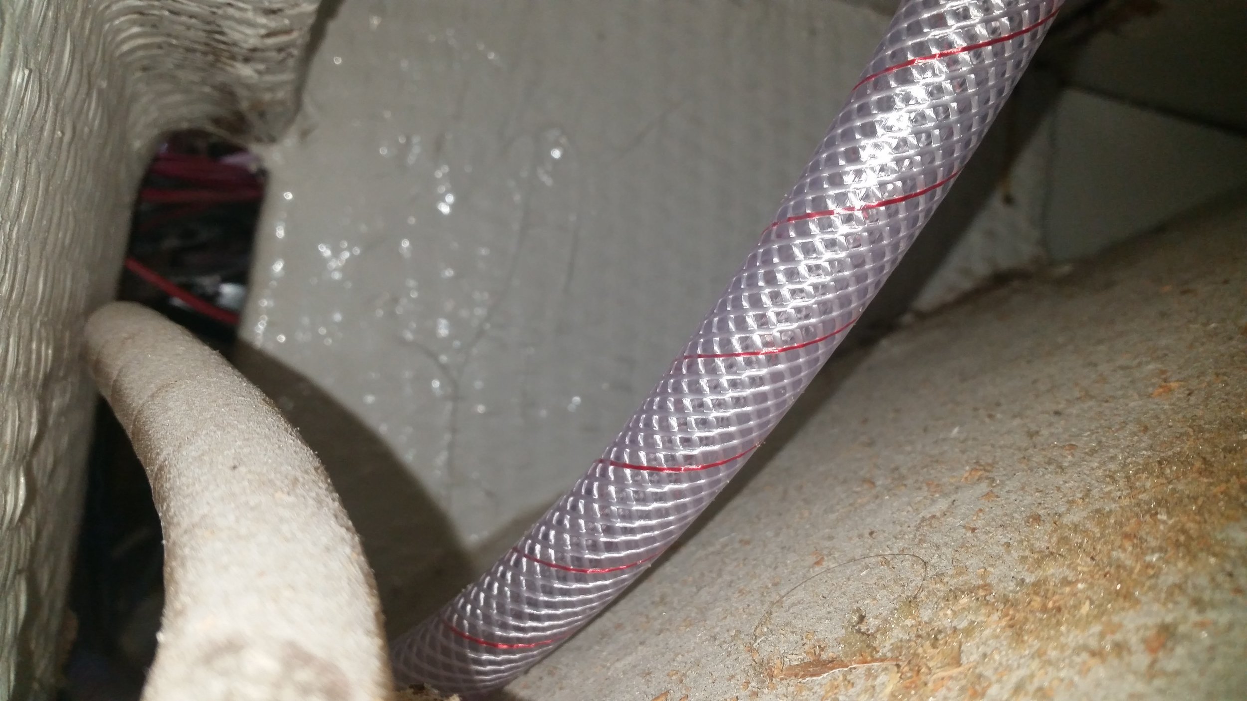
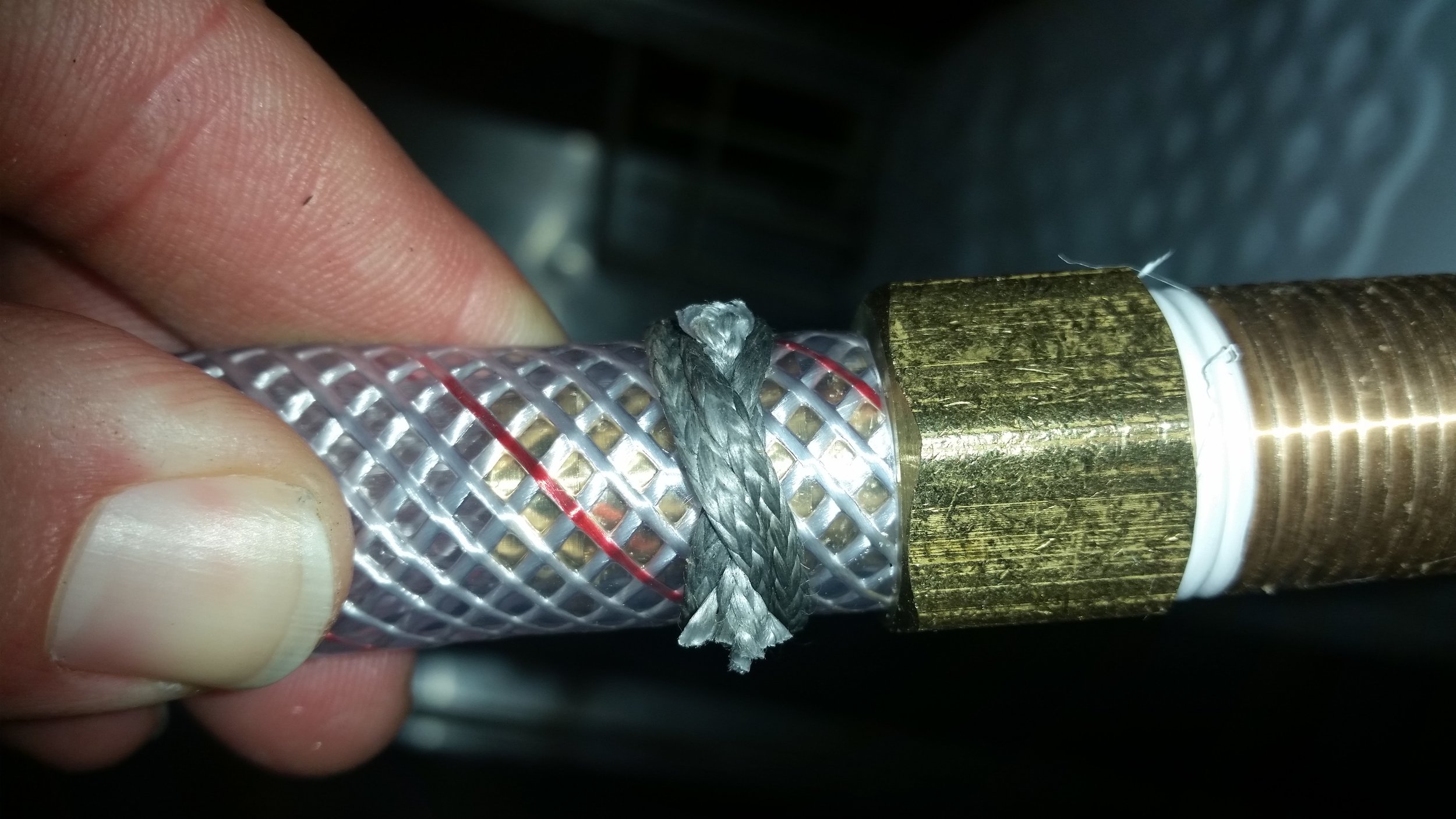
The flexible tank drains via a small 1/2 inch water hose that is led to a high powered water pump. This pump will flow 4 gallons per minute at 60 psi through a hose that will allow us to test the water, and if we like it, dump it into the main tanks. If we don't like it, we can purge it overboard or use it for showering and laundry. Best of all, it keeps us actively watching where and how much the water is going into the different tanks.

The dedicated water pump was mounted under the galley sink on a bulkhead where the hose to feed the tanks could easily be stowed.

The long hose is able to reach all the tanks in the boat, even the tanks located under the V berth in the bow. The ball valve makes it easy to turn the water flow on or off to facilitate filling each tank to capacity without getting your hands in the tank. The pump can flow 4 gallons per minute at 60 psi. This would take 40 minutes to fill up all the tanks (160 gallons) at a fuel dock, but we anticipate that it will run much faster since there is no resistance in the system; hopefully decreasing the time we spend tied up to a pier as we refill our water supply.

The long hose tucks up neatly under the galley sink area, allowing us to carry this convenient length of hose without impinging on our daily life aboard.

The plumbing is complete, but we still need to power the pump. This is where my less favorite part of boat projects comes into play. As you may have noticed, I don't particularly care for electronic devices. Mechanical devices have all their parts on display while electrical devices have all their parts tucked away behind insulative barriers, hiding their corrosion and problems as you wonder why it's not working when you need it. 

Nonetheless, the water pump is electric and needs to be wired into the boats electrical system. This involves running a new positive and negative wire from the breaker panel down through all the inaccessible crevices to lead the wire to the pump. The first step is to open the panel up and start fishing wires through the backs of the interior joinery. 

While it may look like a spider web of wires, it actually isn't that confusing. All the positive (red) wires are on the left side, all the negative wires (black) are on the right side. It may be tempting to wire the negative onto another passing negative wire near the water pump, but this is not advisable. Each electrical component should have its own negative wire that runs back to a central negative buss bar.

Now that the pump is plumbed and wired, the rain water collection and distribution system can now be considered complete. All we have to do is wait for our next rain storm to give it a test!  

Converting the Refrigerator into an Icebox

The difference between a refrigerator and an icebox is the presence of a mechanical refrigeration unit. Engine powered or electrically powered, the goal is the same: a compressor changes the pressure of a gas and makes it transform from gas to liquid and back to gas state. The change in state alters the temperature of the refrigerant and can be used to cool the refrigerator. We currently have a refrigerator, but if any component of the refrigerator compressor system should die, we will simply continue on using an icebox.

Most marine refrigerators and iceboxes have a drain hole in the bottom, where any water that collects in the bottom can be drained away. Ours does not, so any ice the melts while inside the refrigerator collects in the sealed bottom. To remove this melted mess, I have employed the use of a manual bilge pump connected to a very long hose that can reach from the bottom of the fridge to the galley sink.

For years, this has been our method of removing any water that accumulates in the bottom of the refrigerator. As you can see, the very long hose is very annoying as food needs to be intertwined around the hose. Moving the hose and stretching it out to the galley sink runs the risk of upsetting the certain foods that might spill or break. Worse yet is when the hose doesn't want to go back into the fridge after the water has been removed.

Adding ice to the fridge will make the refrigeration unit consume much less electricity, but it will also lead to a lot more ice melting and more water accumulating in the bottom of the fridge. More water would imply more frequent pumpings to remove the water from the bottom of the fridge. This will become a significant chore, and it will be one that I am not looking forward to.

To remedy this problem, a drain could be installed into the bottom of the fridge. Drains do decrease the efficiency of the fridge as they are considered a weak point in the insulation and will allow some loss of cold and some entry of heat into the icebox. The most efficient type of icebox would be completely sealed and have no openings. The lid already violates this ideal scenario, so why not add a little more insult in the name of convenience.

A drain in the bottom of the fridge will allow us to remove the melted water with the assistance of gravity. Any water will leave the fridge through the bottom where it will be flushed away down the drain hole and out a weep hose. To prevent any cold air from also escaping, a valve is placed at the end of the hose. With the valve shut, the hole in the bottom of the fridge is sealed and cold air will not leak out of the bottom of the fridge.

Since the stainless steel liner is already installed and surrounded by foam, it is impossible to safely weld a drain into the bottom as the foam insulation can burst into flames with the heat of welding. Instead of burning my boat to the waterline, I instead opted to use a bronze through hull fitting with a hose barb attachment at the end. Bronze and stainless steel are dissimilar metals, but the bedding compound should keep everything isolated, at least enough for my lifetime. If any galvanic corrosion should occur, it would be very minor and probably go unnoticed. 

The largest part of the assembly needs to fit through the stainless steel plate, this means that the hex portion of the barb fitting is our desired hole size. In order to drill such a large hole, I used a step drill that will open the hole progressively larger until it is big enough for the hex to fit. I started out with a small pilot hole to help position and start the step drill, then proceeded to ream out the bottom of the fridge. 

With the hole made, there was sufficient space to clear the hose barb. The next step was to drill through the six inches of foam and then the plywood bottom of the fridge. I needed to use a drill bit extension as standard drill bits were not long enough to reach the wood at the bottom of the fridge. 

I didn't need to worry about drilling through the bottom of the fridge and then springing a leak as there is a considerably large dead space under the refrigerator. While this area does look roomy, there is no appreciable access to it. There are two small holes that access this area, one is the hole in view. The lack of access makes this large and cool space inaccessible and precludes us from using it as storage. If you ever need to inspect the contents of a small hole, simply insert a cellphone camera into the hole and snap away. When you withdraw the phone, you can view the contents of the forgotten space. 

The hole for the drain was drilled and all the sawdust fell into this dead space. This small mess will stay there for the rest of time as there is no way to reach inside here and clean it. The hose was fished down through the drain hole and out the access hole. With the hose run, it was time to attach the hose to the through hull fitting. 

Instead of using a bulky hose clamp, I opted to use a low profile knot that will crush down on the hose and permanently attach it to the hose barb. The knot is called a Double Constrictor Knot and when tightened using two sticks, it is impossible to untie. The tails of the knot were attached to two larger objects using marlin spike hitches that would allow me to pull on the tails with all my might. Tying the knot with a line made out of dyneema ensures that this knot will last as long as Wisdom does. 

20170225_134239.jpg

With the tails cut off close to the knot, the entire clamping system is no larger than the hex head of the hose barb. With all of this in place, it is now time to apply the bedding compound and smooth it all together. 

I used 3M's 5200 for the bedding compound in this situation for a few reasons. First, it will seal up everything and make sure that no water leaks into the insulating foam, saturating it and creating a huge mess to repair. Second, I was unable to access the opposing side of the through hull fitting to attach the retaining nut. 

5200 is considered a permanent adhesive sealant. This means that not only will it keep out water, it will also glue the components together permanently. I would love it if the through hull fitting were glued in place since it has no mechanical fasteners holding it there. Yes, a drain is under very little to no stress, but if it were to move it would certainly cause a leak that would go unnoticed for a while. 

I rarely used 5200 because of its permanentness. I have seen winches that were needed to the deck with 5200 be removed. The bolts were removed and the winch would not budge. After a lot of prying and pulling, the winch finally came free of the deck, but it brought the top layer of deck skin with it! That's right, the junction of the winch base and 5200 remained and instead the fiberglass deck ripped up with the winch and make a nasty hole that needed to be repaired. When 3M says an adhesive is permanent, they mean it! 

For most bedding situations I opt for Boat Life Life-Caulk which is a polysulfide. Polysulfide is not an adhesive, it is only a sealant. It will remain flexible throughout its life and will survive a lifetime exposed to the suns harmful UV rays. If you ever need to remove the bedded component, all you need to do is unfasten it and remove it. The polysulfide will yield quickly and peel off without leaving any form of a mess. 

If I feel the need for more adhesive qualities in the bedding compound to complement the mechanical fasteners, I will use 4200 by 3M. It is just as good a sealant as 5200, but it is not a permanent adhesive. Don't get me wrong though, if you need to remove something bedded with 4200 you will still think it is permanent, just that when you give it enough persuasion, it will yield and remove without damage to the surface it was mounted to.

With the drain installed, I needed to keep some pressure on it while the 5200 set. I rigged up a contraption that used some socket extenders and the block of mahogany I used to tighten the double constrictor knot. This applied enough pressure to keep everything pushed down and to ensure that no voids would develop during the cure time. 

On the other end of the drain hose, I attached a small gate valve. The valve is to serve two purposes: keep water from leaking out, and keep air from leaking out. 

If the ice were allowed to melt and drip into the bilge, the bilge would always be wet! The valve allows me to control when the fridge is to leak out its contents and where. I can now drain the water into a cup that can be used to chill wine!  

Keeping the valve shut also prevents any air from escaping. The colder air will settle to the bottom of the fridge, and if it is allowed to escape through the drain hose, the fridge would become awfully inefficient! By keeping the valve closed, I can keep the cold air in and the warm air out of the bottom of the fridge. The only time that the fridge will experience a drop in efficiency is when I open the valve and drain out the water that has accumulated in the bottom. Until then, the unit will remain closed up and sealed as we attempt to keep cold stuff cool for longer! 

Rainwater Plumbing: Deck to Tank

Getting the tank in the bilge was pretty straight forward. Getting the water to the tank is a little more complicated. 

To accomplish this task, a small aqueduct needed to be constructed. Nowhere near the level of grandeur of the ancient Romans, but the same principles still apply. In general: the starting point needs to be higher than the ending point, there should be no inclines, and tight bends should be reduced.

Having the deck as our starting point and the bottom of the bilge as our ending point makes the first point easy to accomplish. Now we just need to make sure the flow rate stays adequate during the entire journey.

Water flows downhill. If there is any incline, the speed of the water will decrease and flow problems will ensue. To keep the speed of flow adequate, water needs to drop rapidly to gain speed that will shuttle it along the less declined sections. With this speed, the water will then flow quickly to the water tank down in the bilge.

Tight bends are another problem, simply because of the added resistance they impart on the passing water as the fluid attempts to make twists and turns.

With these concepts in mind, it is fair to say that plumbing the water tank is rather straight forward. This pleasant state of mind will take you all the way to the starting point of the project where you soon realize that sailboats are a collection of compromises.

The low spot on the deck is next to the cockpit, so the hose will begin at deck level and drop down quickly as it makes its way to the bilge. This will give the water a quick burst of speed that will help make everything else flow nicely. From the cockpit lazarettes, it then needs to work its way past the steering mechanism and into the bilge where it reaches the flexible water tank. This is where the problems begin!


The starboard side was easy. The old diesel exhaust hose used to run through the hole visible at the top of the area. The port side is rather packed full of hoses. The three hoses visible are the cockpit scupper drain, cockpit manual bilge pump and electric bilge pump hoses. Adding an extra hose on this side will prove challenging.

The hoses all need to run over the top of the metal frame to the steering quadrant to avoid interfering with our steering, and this makes the available hose space even more limited.

The final decision was to drill a new hole below all the other three holes on the port side and then have the hose ride up over the metal frame and then quickly back down again. Hopefully, the water will have enough speed that it will be able to flow up and over the little hump and into the tank without much issue.

Once past this point, the hoses are joined in a Y where they follow along as a single hose to the tank. From this point forward, everything is a steady decline with no upsets on its way to the water tank.

The next step will be getting the water out of the tank so we can use it!