Battens and Siding

The battens that hold the wrapping in place need to be removed as you install the new siding. You may be tempted to just install the siding over the battens, but this will lead to long term problems. 

Siding installed over the battens will look undulated. The battens would be high spots and the gaps between would be low spots. The result is a wave look to the walls that is only remedied by removing the siding, removing the battens, and installing new siding once again.

Removing battens is very easy. All you need to do is rip it off! The batten will bend easily and snap off at the next screw that holds it in. Be sure to remove the screws as they will also lead to the same wavy look you are trying to avoid.

You don't want to remove all the battens before you begin because the battens do help hold the paper in place until you reach there with the siding. 

You can see the torn batten showing at the top of the picture. The dark black lines were where the freshly removed battens were covering the tar paper. The tar paper under the battens was shielded from the sun and never faded.

Removing battens is very easy and can be done incrementally as the siding goes on the tiny house. As the siding reaches the next set of screws, the battens are simply snapped shorter and the screws removed. Then the tar paper was instantly covered by the siding planks, tucking them away behind the siding forever removed from sight.

Medullary Checking

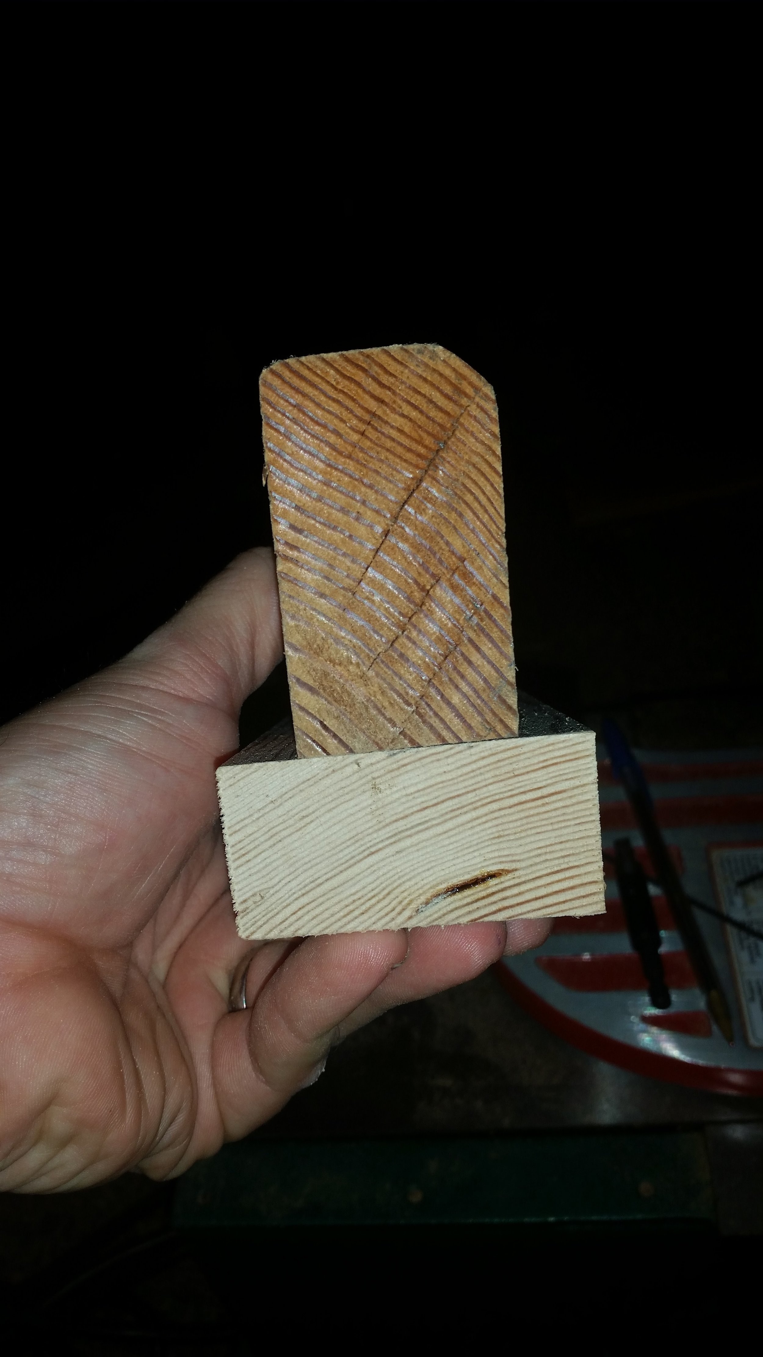
Medullary checking occurs perpendicular to the direction of the annular rings in the wood. As wood dries out and seasons, it will shrink. If the wood shrinks too quickly or too drastically, it will split and open up into what are called "checks". They are very visible on large timber and posts, as these timbers will shrink considerably and quickly, resulting in the development of checks.

While checks can be unsightly on fence posts, they present more of a hazard on boats. First, these checks will allow water to pass through the wood and cause leaks to form. Second, any fasteners that are in the check will become loose!

To reduce the risk of checking, some easy steps can be followed:

  • Don't use boxed in heart wood.
  • Don't use green wood.

The heart of a tree will almost always check in a characteristic plus sign. The checking will usually run all the way out to the sides of the timber, resulting in a piece of wood that wants to be quartered. If you select a timber that does not have the heart boxed in the center, the risk of checking is greatly reduced. If the timber has a heart, try to orient your cuts so that the heart will be cut out of the finished product. This will remove the heart and the risk of severe checking as the wood dries out.

The other method to avoid checking is to properly season your wood. If you use wet, green wood, it will dry out too fast and shrink. As it shrinks rapidly, it will check and ruin your finished product. To reduce this issue, you want to season the wood slowly. Seasoning is simply the act of drying the wood in a controlled manner. The rule of thumb is one inch per year. If your lumber is 1 inch think, it will take a year to dry out properly. If your lumber is 2 inches thick, it will take 2 years to dry out properly.

This is a rule of thumb. The truth is the wood is dried by the relative moisture content of the room it is stored in. Letting the wood dry slowly will prevent checking by controlling the rate at which it shrinks. If your storage area is rather humid, the wood will dry slower. Likewise, if the room is bone dry, the wood will dry out very quickly.

You may be wondering what difference does it make if the wood seasons in a room or on a boat? It dries just the same, right? Wrong. The reason seasoning reduces checking is the wood dries evenly. If you take a green piece of wood and install it on the boat as a frame, the three sides that face the inside of the hull will dry out as they are exposed to a lot of air, but the side facing the planking will not dry. Three of the four sides will dry out quickly and shrink while the fourth side will remain wet and not shrink as much. The irregular shrinkage will lead to the development of checks. If the wood were allowed to dry out entirely in a room where all four sides are exposed to the air and can shrink together in a controlled manner, the incidence of checking is greatly reduced.

If you do all of this perfectly, and use wood with no heart that has been well seasoned, the risk of developing checks in the future is greatly reduced but not eliminated. 

To mitigate the risks of fasteners coming loose because the wood they are in checks, make sure that the screws are oriented properly to the grain. If you insert the screw with the grain, so that the screw runs parallel to the rings, the screw will have very little holding power and runs the risk of causing the wood to split along the grain. If you insert the screw perpendicular to the rings, it will have the most holding power, but will also be set in line with the medullary rays. Medullary rays run perpendicular to the rings as do the medullary checks. While the screw may hold well at first, it may lose holding as checks develop in the future.

The alternative is to set the screws at forty five degrees to the annual rings of the wood. This will place the screws through the rings, giving you the holding power of driving the screw through the rings while not lining up perfectly with the medullary checks that may develop. Now the screws are oriented at an angle to any checks that may develop while still offering an acceptable amount of holding power.

As you may have imagined, this is why quarter sawn lumber is so popular. You can place the screws into any of the faces and the screws will always be oriented diagonally to the annual rings of the wood. This is why quarter sawn lumber is preferred when being used on a boat.

Replacing your Halyard

Replacing your old halyards is a crucial part of maintaining your running rigging.

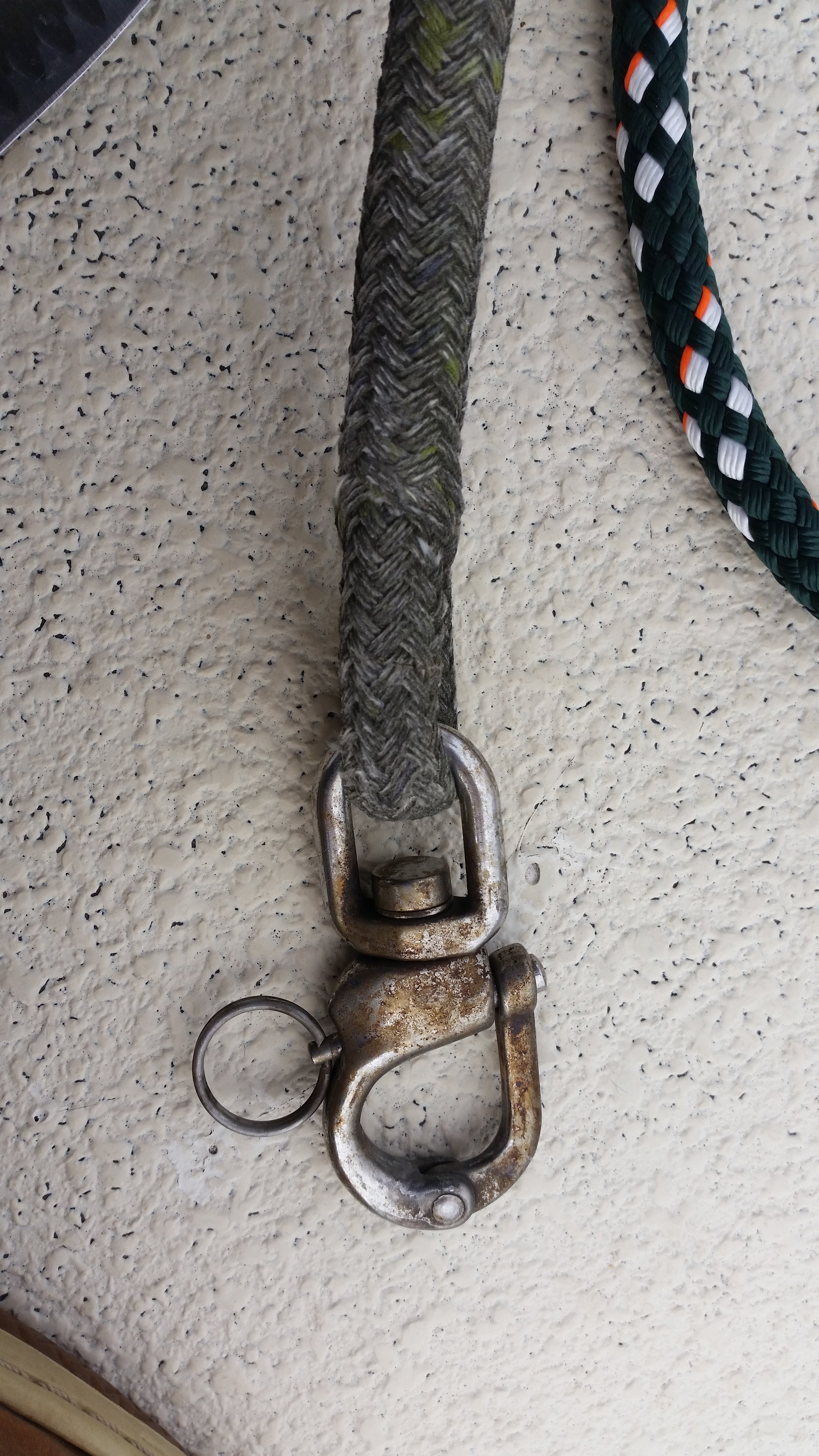
This halyard was originally white with blue flecks. The owner wanted to reuse the same snap shackle. 

Replacing your halyard is very easy. The steps are simple and easy to carry out.

  1. Tie a messenger line to the lazy end of the halyard
  2. Pull the halyard (and messenger line) through the mast and out the mast head shiv.
  3. Tie the messenger line to the lazy end of the new halyard
  4. Pull the new halyard back through the mast head shiv and through the mast

That's all you need to do to install a new halyard! If your old halyard is looking worn, don't hesitate to remove it and replace it.

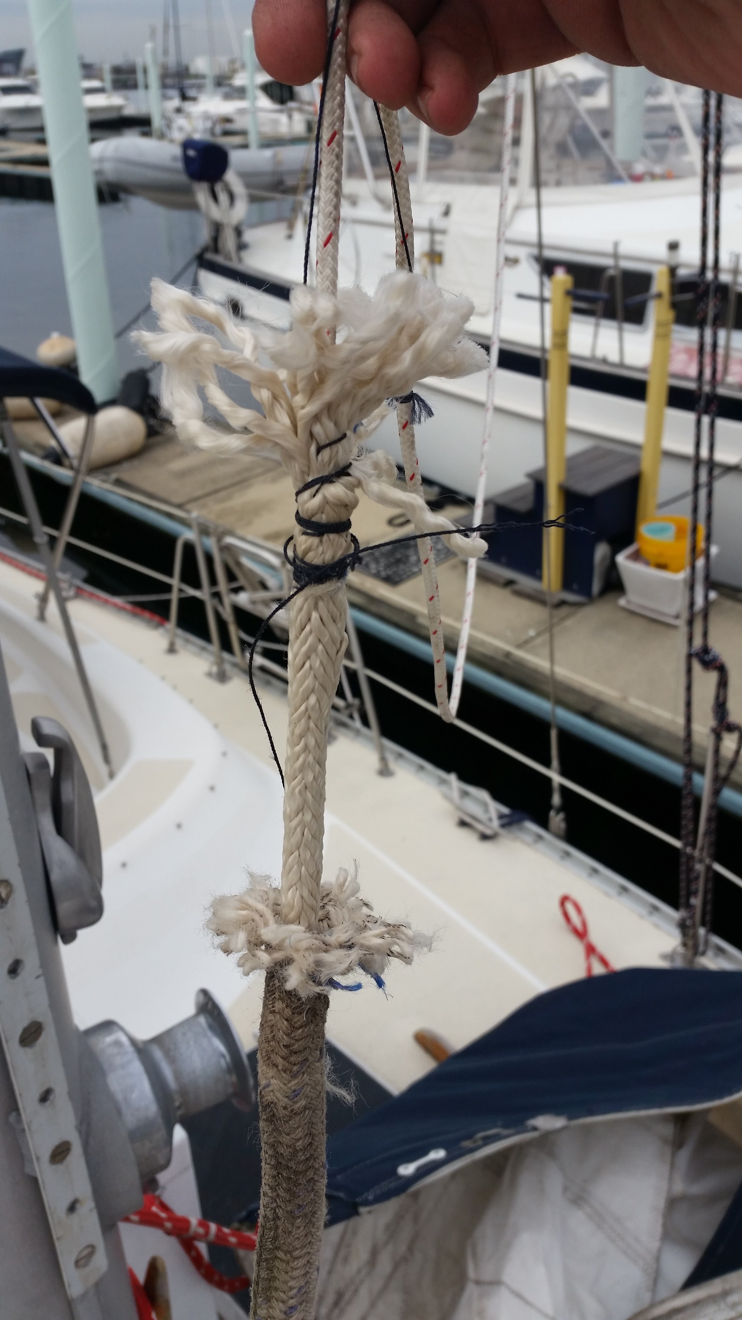
The most important thing in this process is to properly secure your messenger line to the end of the halyard so that they don't separate part way through the replacement.

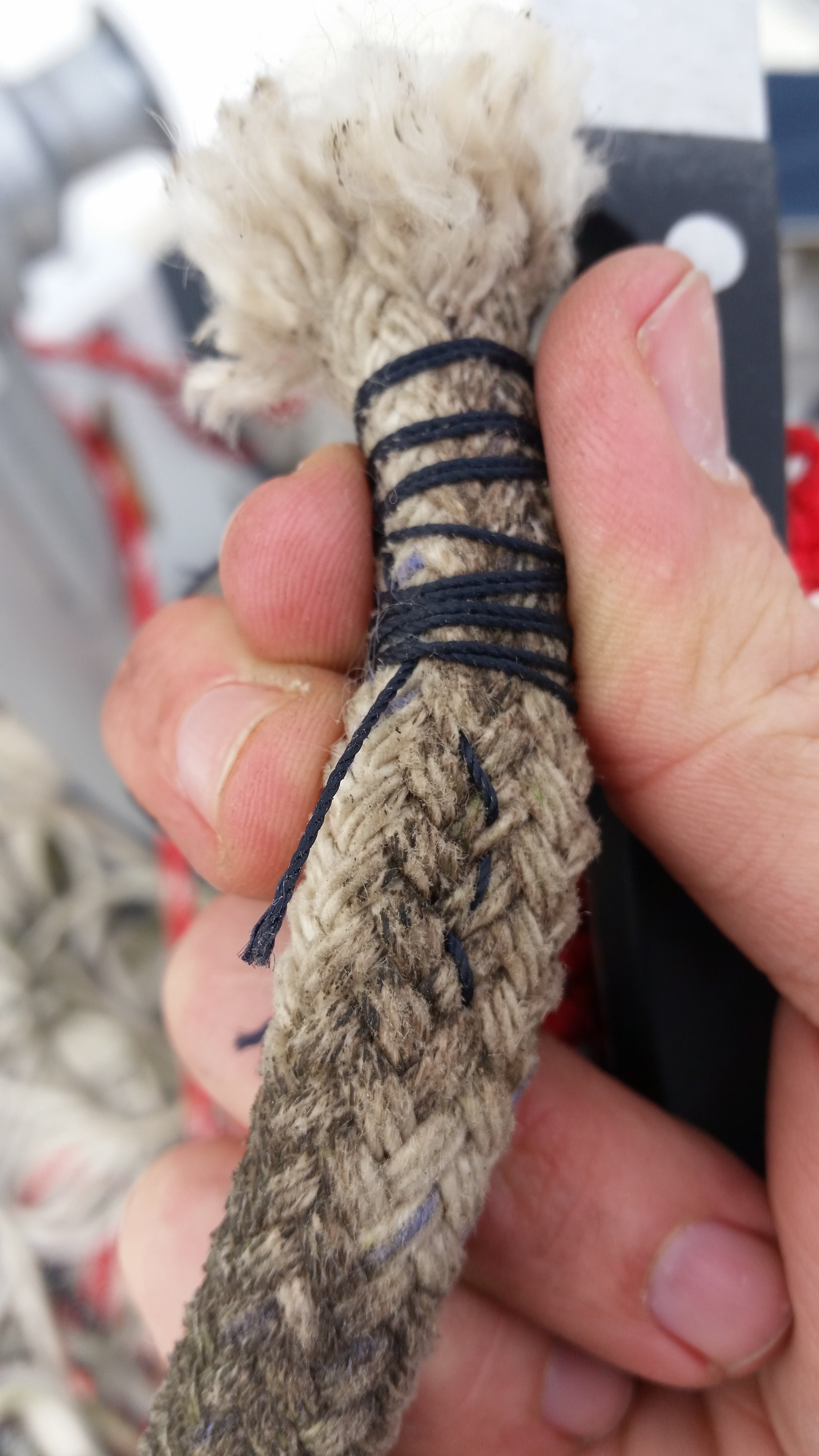
The messenger line is stitched to the core and the cover is sewn to the end, allowing us to pull it back out if needed. This makes a very secure and fair connection that wont bind on anything inside the mast during the process.

Tiny House: Windward vs Leeward Sides

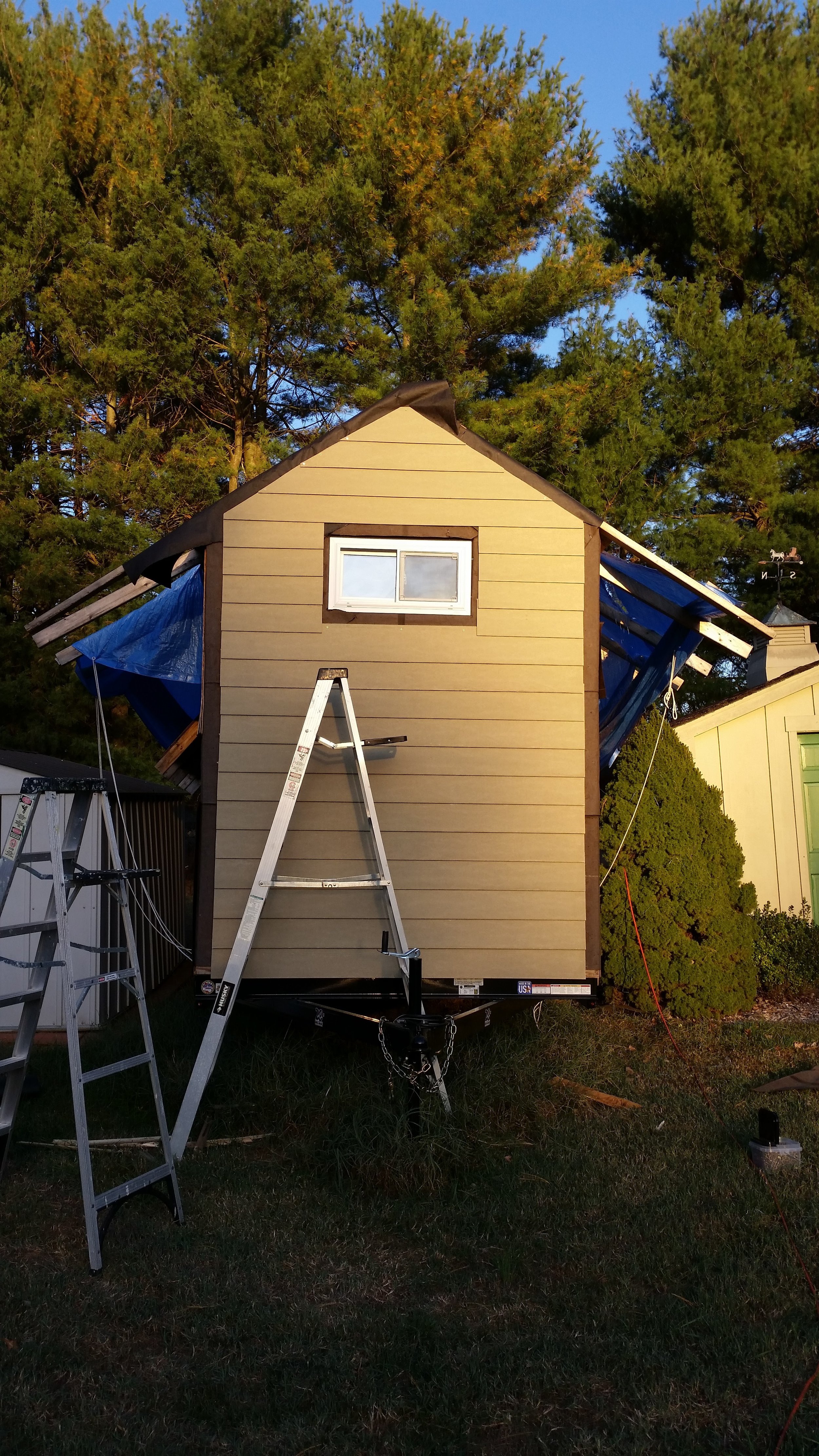
The side of the tiny house that faces the tow hitch should be considered the windward side. The side that faces away from the tow hitch should be considered the leeward side. This is because when you tow the tiny house down a highway, the tow hitch side will face directly into the apparent wind and the other side will face away from the apparent wind.

Identifying these sides of the house is more than an academic exercise, it is a functional exercise. The siding on the windward side needs to be much more secure because it will frequently be faced with very high wind speeds! 

The siding on the windward side needs to be fabricated out of solid planks that run the full width of the tiny house. There should be no butt joints on this side as these joints are weaker in high winds. 

Windward side

Windward side

The leeward side is much more forgiving. There will be very little direct wind on this side and butt joints are allowed. 

This side is sided by all the left over off cuts from the windward side. These pieces are simply set and fitted to one another, making them reach and fit the length needed.

You want to stagger the butt joints though, that way they blend in and disappear into the wall. If you set all the but joints in a single column, it will be very noticeable and will be considered rather unsightly.

Stern Knee

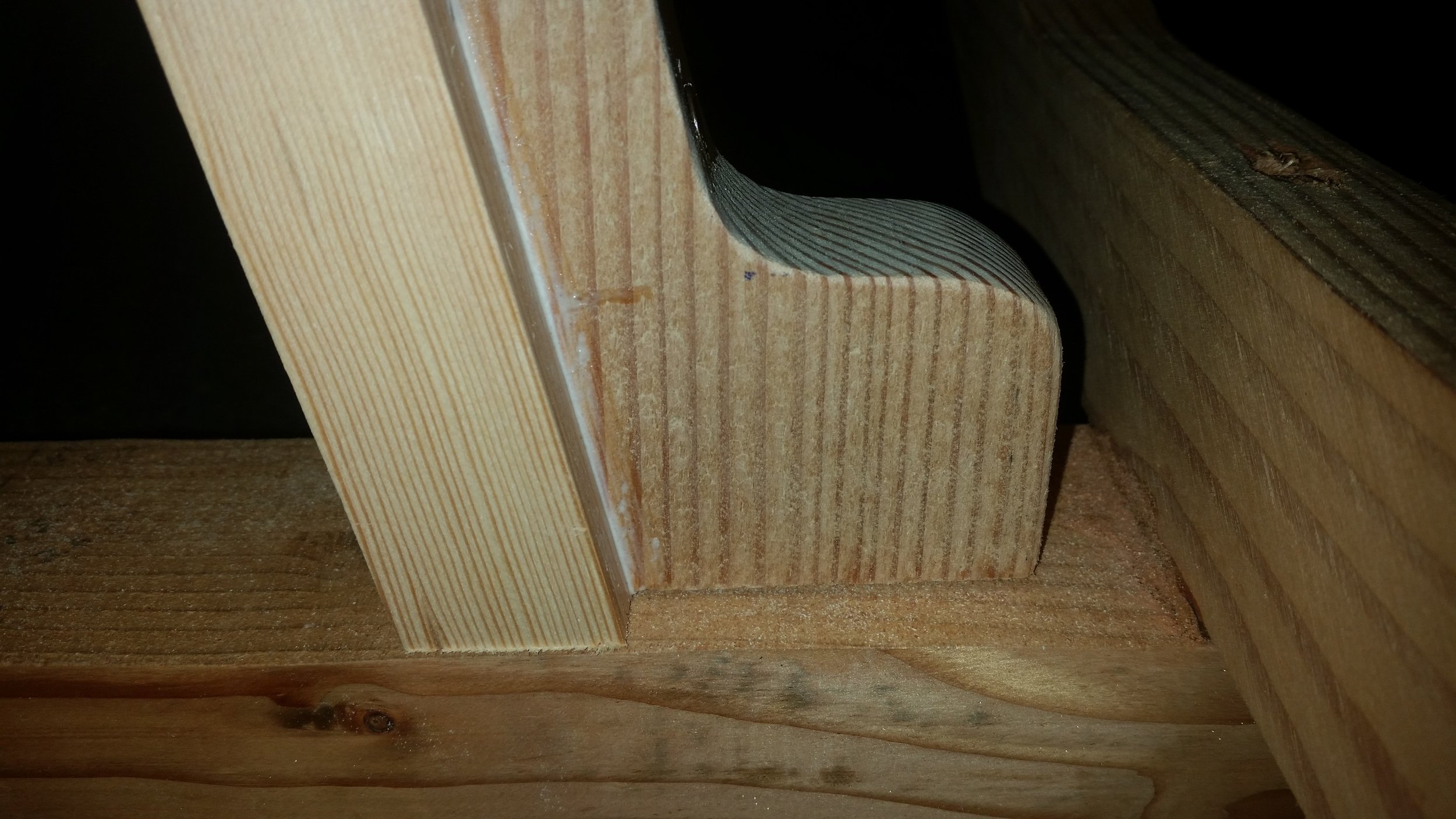
The stern knee is the structural support that helps transfer stress and loads from the stern post to the keel. It is made out of a single piece of wood that has vertical grain with a slight angle to it. The slight angle ensures that the medullary checking that will occur will form diagonally across the knee and not in the same direction as the fasteners.

The stern knee attaches to the end of the keel via a large and strong bronze lag bolt and to the stern post via four stout bronze screws. The transom planking will be attached to the stern post, transmitting it's loads to the keel via the stern knee. As you can see, this is a rather important structural member in the dinghy.

To add complexity to the fabrication process, the transom is going to be raked aft with a slop of five inches every twenty four inches. This angle will produce a gentle and pleasing to look to the slope of the transom. This angle is also ideal for. The mounting of an outboard motor, which we will do in emergency situations.

The stern knee and stern post need to mate perfectly flush with the flat keel. To get the angle of the sloping transom to mate perfectly with the flat keel, I used a variety of squares and calculations. I know that the freeboard is going to be eighteen inches high, so the sternpost was set in a square where the top of it passes over the eighteen inch mark. The bottom of the sternpost was scooted over to the three and three quarters mark, as this distance follows the same slope of five in twenty four. I pinched the stern post to the square and raised it off the surface just a bit so I could mark it from the underside with a pencil.

The line drawn on the side of the stern post now represents the correct angular orientation for the bottom of the sternpost to mate perfectly flat with the keel.

This line was cut on the bandsaw and then test fit to the keel. The top of the stern post was left much longer than needed as it is always easier to shorten a board than it is to make it longer. With the angled cut verified, I know that the stern post is long enough and angled properly.

The knee was cut out following the same slope line. The knee is six inches tall, so a slope of five in twenty four would mean that our six inch knee needs to slope over one and one quarter inch.

The block of wood was marked at the top at the six inch point and on the bottom at the on and one quarter inch mark. A straight edge connected the marks giving me the line to cut along to match the stern post's aft rake to the stern knee.

After cutting the knee along the line with the bandsaw, we the two pieces were test fitted. To properly test fit the stern post and stern knee, a square was used, as the top of the stern post should intersect the 18 inch mark and the bottom of the stern post lay flat on the bottom of the square. During the test, the stern post met the mark and the faying surface to the keel laid flat!

The two pieces were test fitted on the keel to verify that they are true and mate up to the faying surface of the keel properly.

Since they mated well, it was time to connect the stern knee to the stern post. I drilled pilot holes through the knee which will accept the bronze fasteners. The holes are set staggered to avoid causing a crack in the knee. If you set all four screws in a vertical line, the knee can split along the grain and fail its purpose. By staggering the screws placement, the rest of splitting the knee is greatly reduced.

With the holes drilled and any splinters sanded off, it is time to drill the pilot holes in the stern post. The top pilot hole was drilled by first marking the sternpost with the drill running in reverse. Running the drill in reverse minimizes the risk of the drill bit walking aroud, ruining your alignment. Running the drill in reverse will produce a very notable mare on the stern post. Once the stern knee is removed, you can mark your pilot hole without any risk of misalignment.

With the first hole ready, the stern knee was set back onto the post and the bronze screw was inserted most of the way. This will keep the entire unit aligned and in place while the other three holes are made.

With the top of the knee supported by the screw and the bottom of the knee supported by a clamp, the second pilot hole could be created in the lowest screw hole and its screw inserted. Now the knee is securely held in place and the last two pilot holes can be drilled at the same time to speed up fabrication time.

Now that the four holes have been drilled with accuracy, it is time to join the two pieces of wood.. The faying surfaces were coated with a liberal amount of Titebond III waterproof wood glue and some extra wood glue was set into the screw holes. The glue in the screw holes will coat the bronze fasteners as they are driven in and lock them into place as they coat the threads.

With all the surfaces ready for mating, the knee was aligned to the stern post and the four screws were driven home. The four screws will provide enough clamping force, negating the need to use external C-clamps. The excess wood glue squeezed out, ensuring that all the surfaces were sufficiently covered with glue and the excess was wiped off with a dry towel. The glue was then allowed to cure for the next two days without being disturbed.