Rope to Chain Splice

Most windlasses will not accept a thimble connection between rope and chain. Instead, they need to be spliced in a low profile way where the transition from rope to chain goes unnoticed and seamless. 

The rope to chain splice has a lot in common with a long splice, where the lays are removed and replaced to connect the lines. 

FullSizeRender.jpg

To begin, you need to understand a few basic points. First, the length of your splice needs to be at least 2 feet, which means that the start of your splice will occur two feet in from the bitter end.
FullSizeRender.jpg

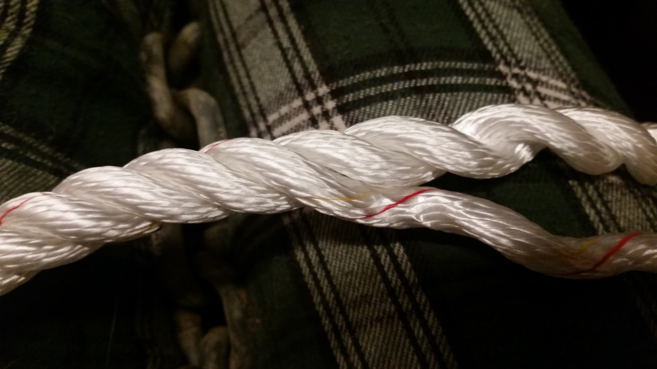
To begin, you will unravel one strand of your three strand rope. The strand will want to unravel, but you must keep it all together. With practice, you will be able to do this on new rope without any added stiffening agents (which is how I am doing it here), but if you have trouble keeping the strands from unraveling, a liberal coating with hair spray might be the answer to your woes. 
FullSizeRender.jpg

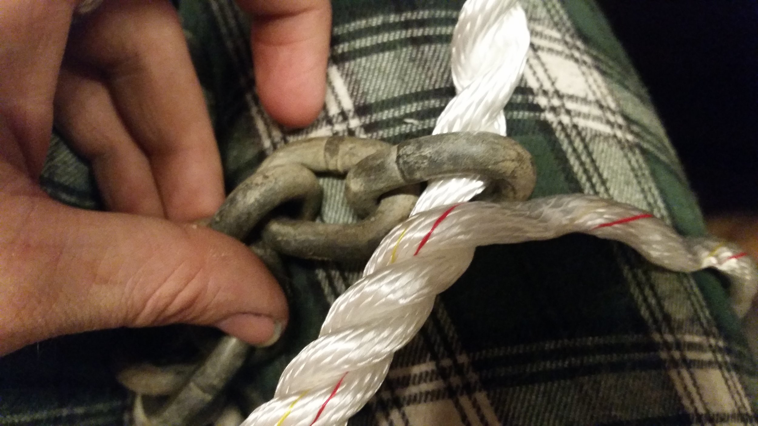
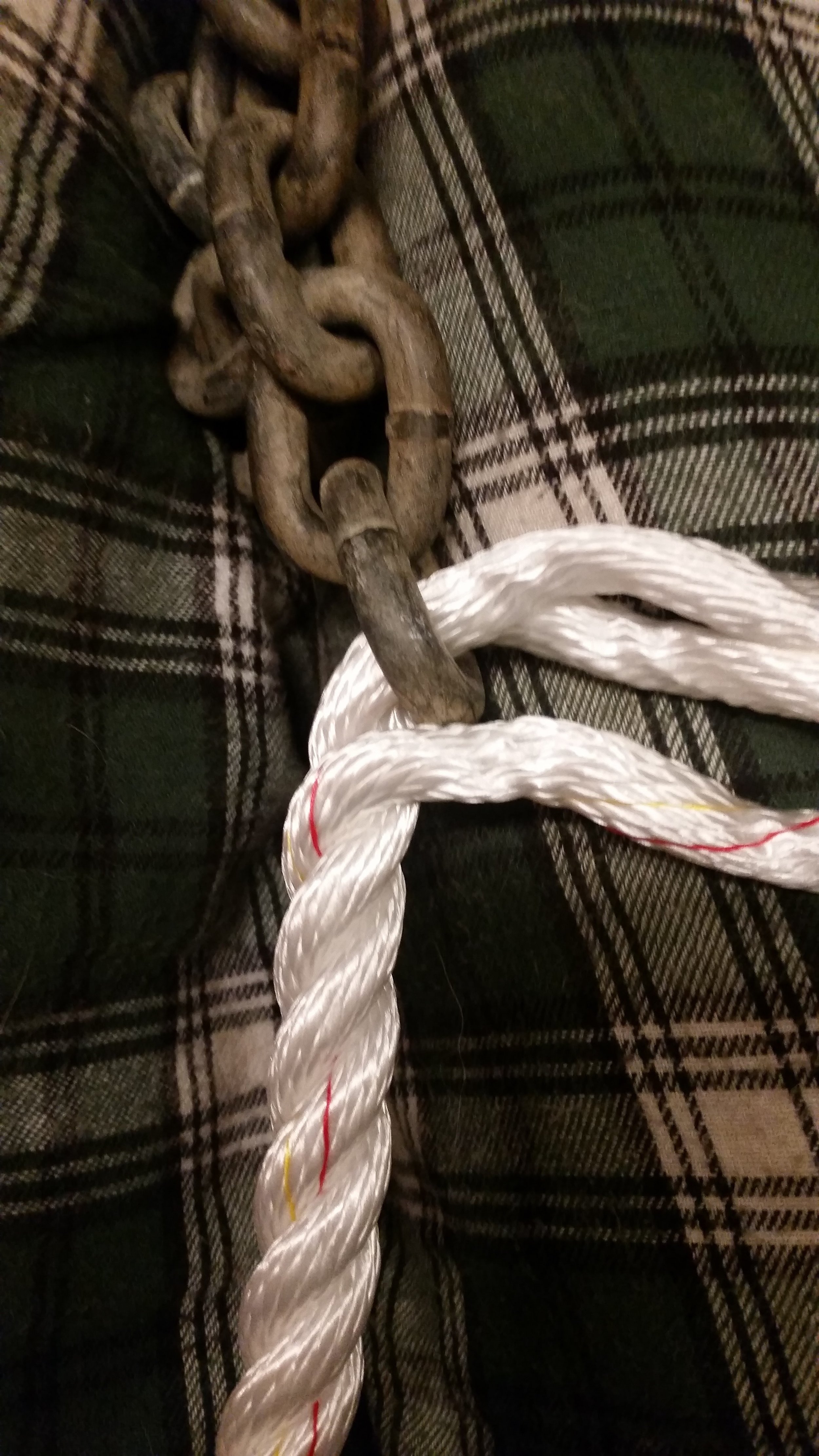
With one strand removed, you now have two strands that are still twisted together. You want to slide the chain link down these two strands until it meets the separated strand. There should be at least 2 feet of tail extending beyond the link. 
FullSizeRender.jpg

Now begins the splice. I like to bend all three strands over to the side and separate the two that have passed through the chain. The strand that is closest to the outside strand will be the strand of interest for this next step.  We will call this one the second strand.

FullSizeRender.jpg

You are going to unwind the third strand, and wind in the closest strand, which we are calling the second strand.

Let me clarify, you will lift out the third strand that did not go through the chain and you will replace it with the strand that is closest to it that did go through the chain. As you lift out the third strand, you will pack the second strand into the groove it has left behind. You will continue this process as you go burying the entire length of the splice, which is at least 2 feet. 

FullSizeRender.jpg

Down the rope you will go, removing the third strand and closely following it with the second strand. 

FullSizeRender.jpg
FullSizeRender.jpg

When you get down to about 5 inches from the end, you will tie a square knot with the third strand and the second strand. The square knot will sit neatly into the groove of the rope, hiding it from view. The tails of the square knot will then be tucked into the lays of the rope at least 3 times. It is wise to taper the tails as you go through each tuck, that way the transition leading up to and away from the knot is gradual and will not foul the windlass.

FullSizeRender.jpg

Back at the chain, you not have the second strand folding over the link and tucking itself back into the rope. The first strand remains however and needs to be addressed next. 

FullSizeRender.jpg

You will take the first strand and tie a half hitch with itself.  

FullSizeRender.jpg

This half hitch will be tightened down.  

FullSizeRender.jpg

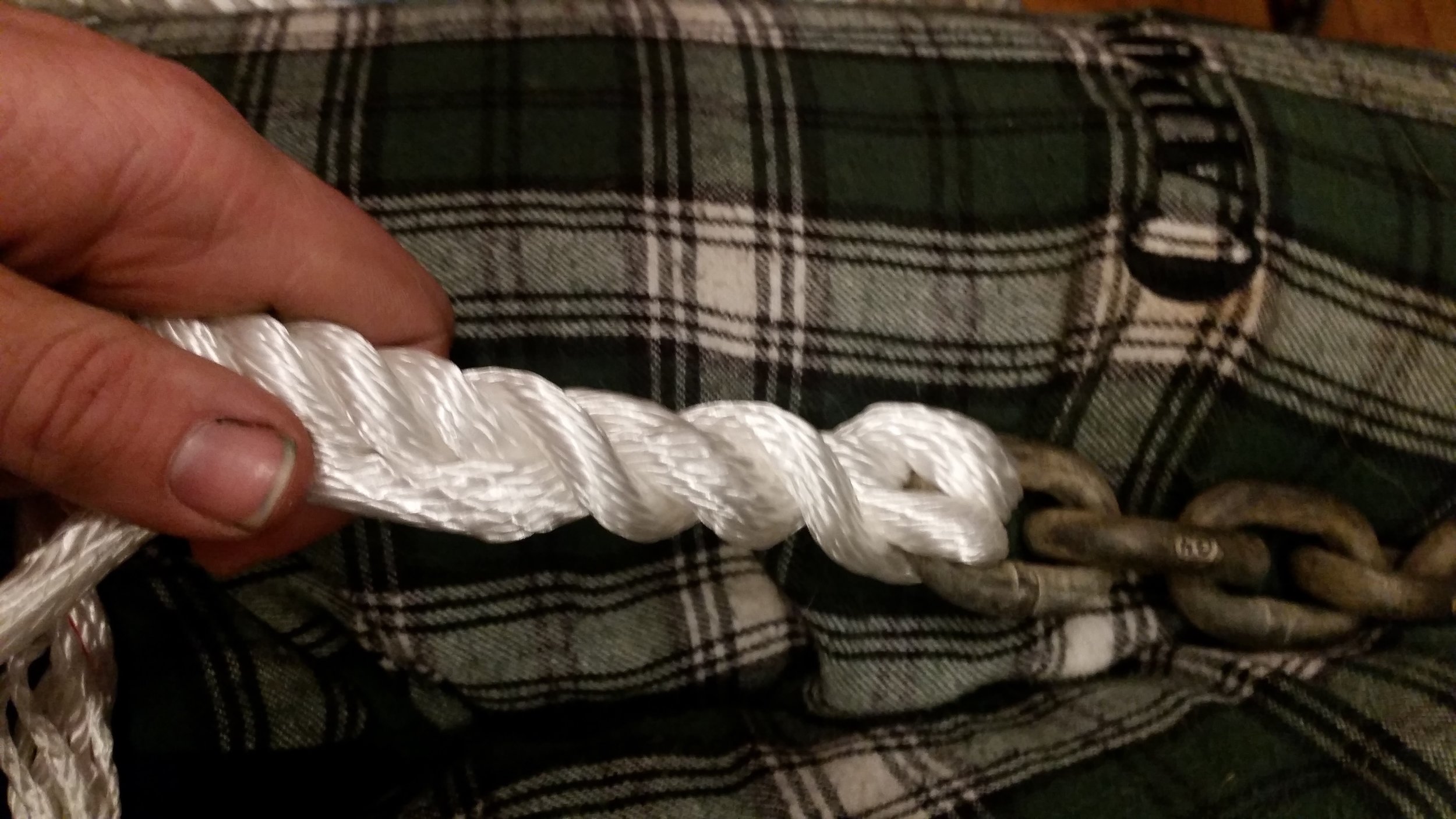
With the knot tightened up, the tail can then be tucked into the lays of the rope. 
FullSizeRender.jpg

The second strand was connected to the rope via a long splice while the first strand is connected to the rope via a short splice. You will want to continue tucking into the rope, at least 5 tucks at a minimum, though 7 tucks would be ideal. 

FullSizeRender.jpg

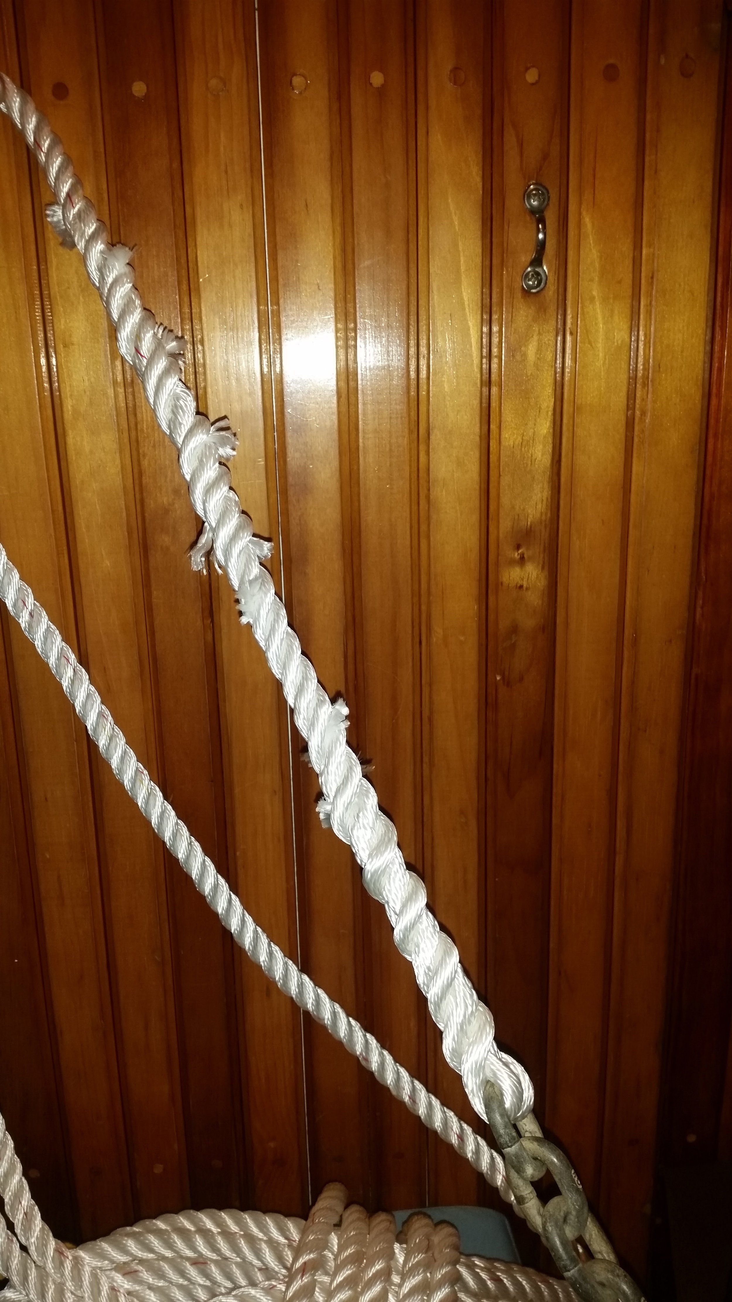
I personally like to tuck the first strand in 7 times and then begin tapering the rope on the subsequent tucks. Tapering is easy, all you need to do is separate the yarns of the strand that you have worked so hard to keep together and count how many yarns are present. Simply divide the yarns into equal quantities and begin snipping them as you go. I like to do three equal groups, as this gives an even taper that is 33% smaller on each tuck. 
FullSizeRender.jpg

The end result is an even tapered splice that will flow through a windlass with ease. It helps to roll and work the rope to get the lays back into their place. You need not to fret much about this though as the load placed upon it by anchoring will work the strands back into their lay in no time! 

You might be concerned though, about only using two strands to hold your chain instead of all three. In a sense, you have reduced the strength of the rope from three strands to only two! 

The truth is, this splice is stronger than the three strands, as the two strands that are working are folded over and tucked back into the rope. This creates a 2:1 on each strand, meaning that there are actually 4 strands holding the force of the chain! That's right, you started with three strand rope and ended up holding the chain with four strands. 

It is very important though that the link be tied tightly in the rope that way it doesn't wiggle around while in service. Movement will lead to chafe, and chafe will saw through any number of strands in a heartbeat.  

By tightening the strands snugly around the rope and splicing them back into the rope, you will create the strongest rope to chain connection possible without the use of a thimble and with the ability to flow through a windlass undetected. 
Reefline Setup, a Common Mistake

FullSizeRender.jpg

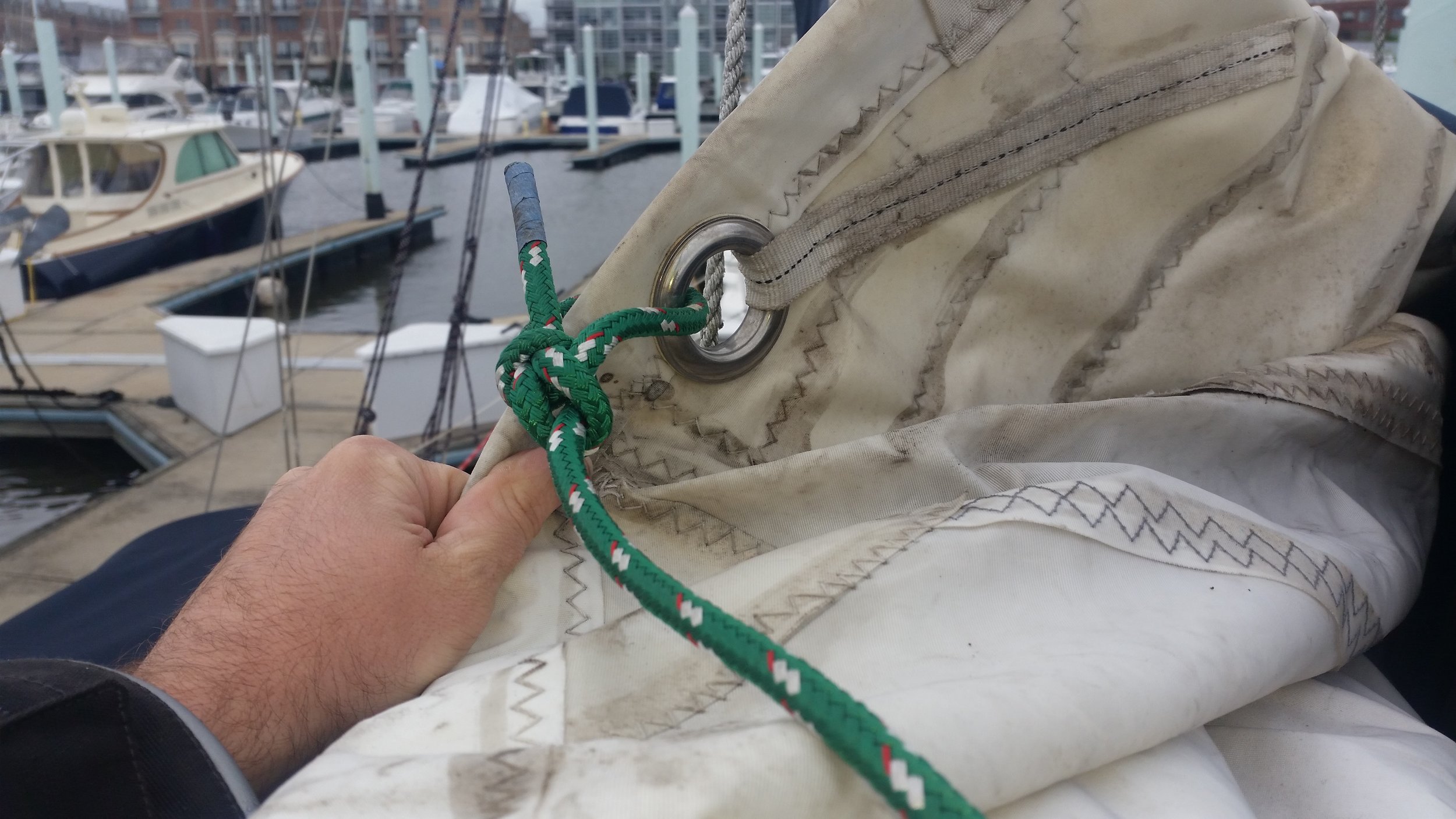
It is very common to see the clew reef line simply tied to the cringle on the leech. This may look fine but it is actually incorrect. 

The correct method is to tie the clew line to the boom, lead it up through the cringle, back down to the cheek block, and then forward along the boom.  

You might be thinking, what is the harm, both methods pull the clew cringle back and down. The biggest fault here is the clew line is rather small for the task at hand because it is designed to be passed through the cringle. When you pass it through the cringle, it instantly creates a 2:1 system, where the force on the clew line is evenly distributed between both lines. This means that if you have 1000 pounds of force on the clew line, each section of the line is only subjected to 500 pounds. 

If you simply tie the clew line to the cringle, all the force is put on that line. In our example, that means that the little line now needs to resist the full 1000 pounds when the designers were only calculating its lost at 500 pounds. 

This is a very simple and common mistake, which is why you should inspect your own reef line setup to make sure you don't have a bowline tied to the clew cringle and instead pass it through the cringle and tied to the boom. 

Attaching to a Spar

It's really easy to go out and buy hardware that will attach to your spar, be it your boom or your mast, but it gets a bit complicated to attach them.


FullSizeRender.jpg

Sure, you can just screw it onto the spar and continue on with your life! In a few months, that fancy new piece of hardware will fall off the spar and be covered in a white powder. Upon further inspection, you will notice that the holes you drilled are full of this white powder and you can't to get the screws to bite when you try to reattach it. 

What has happened is known as galvanic corrosion. It is the corrosion between two dissimilar metals, in this case, the aluminum of your spar and the stainless steel of your component and fasteners. The two metals are reacting and eating each other away like zombies in a horror movie! 

To avoid this horrible fate, you have a few options:

1. Only use like metals. 

2. Do not let dissimilar metals touch.  


Option 1 sounds pretty straight forward. If your spar is aluminum, so should be your components and fasteners. The problem with this plan is aluminum is not a very strong metal and an aluminum cheek block attached with aluminum pop rivets would sheer right off the side of your boom at the first sign of wind! 

This is why high strength components are always stainless steel. Even if the component is made out of aluminum, they will still recommend using stainless steel fasteners to achieve the needed sheer strength required to hold the component in place. 

Option 2 sounds like something out of a science fiction movie! How will you keep two items from touching if you are connecting them? The secret is to use barrier layers in between them, this way they sit up next to each other but will not touch one another. 

The cheek block shown in the top picture was attached to the boom with nothing separating the stainless from the aluminum. This was just to fit the piece and get all the holes drilled. With the holes drilled and the screws fitted, the entire assembly was removed to add the separation layer. 

FullSizeRender.jpg

What we have here may look like a mess, but it is actually a collection of goodies that will keep the stainless from touching the aluminum. Teflon tape, also known as plumber's tape, is laid out over the entire back of the block. This will provide a base layer of separation between the two components.  

The next layer of separation is polysulfide that is piled into the middle of the block. This overfilled amount of material will ooze out over all the surfaces and provide an additional layer of separation and keep any water from getting in between the block and the spar. Polysulfide is great because the excess simply oozes out and is then allowed to cure. Once cured, it can be cut off for a clean, professional looking installation. 

The brown stuff in the corners is Lanocote. This stuff should really be called "wonder grease" because it does everything you could ever dream of, and it's non-toxic. Lanocote is just wool nap, the grease that sheep produce to keep their wool waterproof. This stuff is probably the only material that you can smear on with your finger and not worry about getting cancer from it in 20 years! It acts as a separating layer, anti-corrosive, and anti-galling.  Best of all, Lanocote is very inexpensive!

I put Lanocote in the corners since these are the only parts that are actually going to touch the spar. The rest of the plate is merely "close" but not in actual contact. The Lanocote also helps hold the teflon tape in place while the block is being positioned, that way it doesn't slip out of the way when you are not able to see it. 

All of these layers might sound wonderful, but there is still one serious fatal flaw in this setup. The screws themselves are stainless steel and will be in the most intimate of contacts with the spar. They have to be holding onto the aluminum or the block will fall off!  

The secret here is once again, Lanocote. Dipping the screws in the pot of Lanocote will pick up a lot of material that will coat all the surfaces of the screw. The Lanocote will get into all the nooks and crannies between the threads and down the shank, everywhere that the aluminum will also be in contact. 

When you drive the screw into the spar, the Lanocote will coat everything and provide all the necessary qualities needed to isolate the two metals while still allowing them to grab onto each other. This will prevent galvanic corrosion and keep all the metals happy, granting you a long service life with happy components.  

You might think that this must be too good to be true. How can such a wonderful material be inexpensive and easy to use?! Unlike other more expensive isolation creams and gels that can be purchased, Lanocote will stand up to the test of time. I have removed old components that were attached with synthetic isolators, such as Loctite, and found signs of galvanic corrosion beginning. On that same note, I have removed components that were installed 20 years ago and there were no signs of corrosion between the aluminum spar and stainless steel fasteners. The Lanocote was still moist, just like the day it was applied! 

If you ever need to attach two dissimilar metals, be sure to apply a liberal coating of Lanocote between them to extend their service life and give you peace of mind that all your boats metals are happy. 

Converting to Lines Led Aft: Part 7, Running the Lines

After all the associated hardware is installed, the last step is to actually run the lines back to the cockpit! This is the moment of truth, where all your planning comes into play and you get to see how it all pans out.  

FullSizeRender.jpg

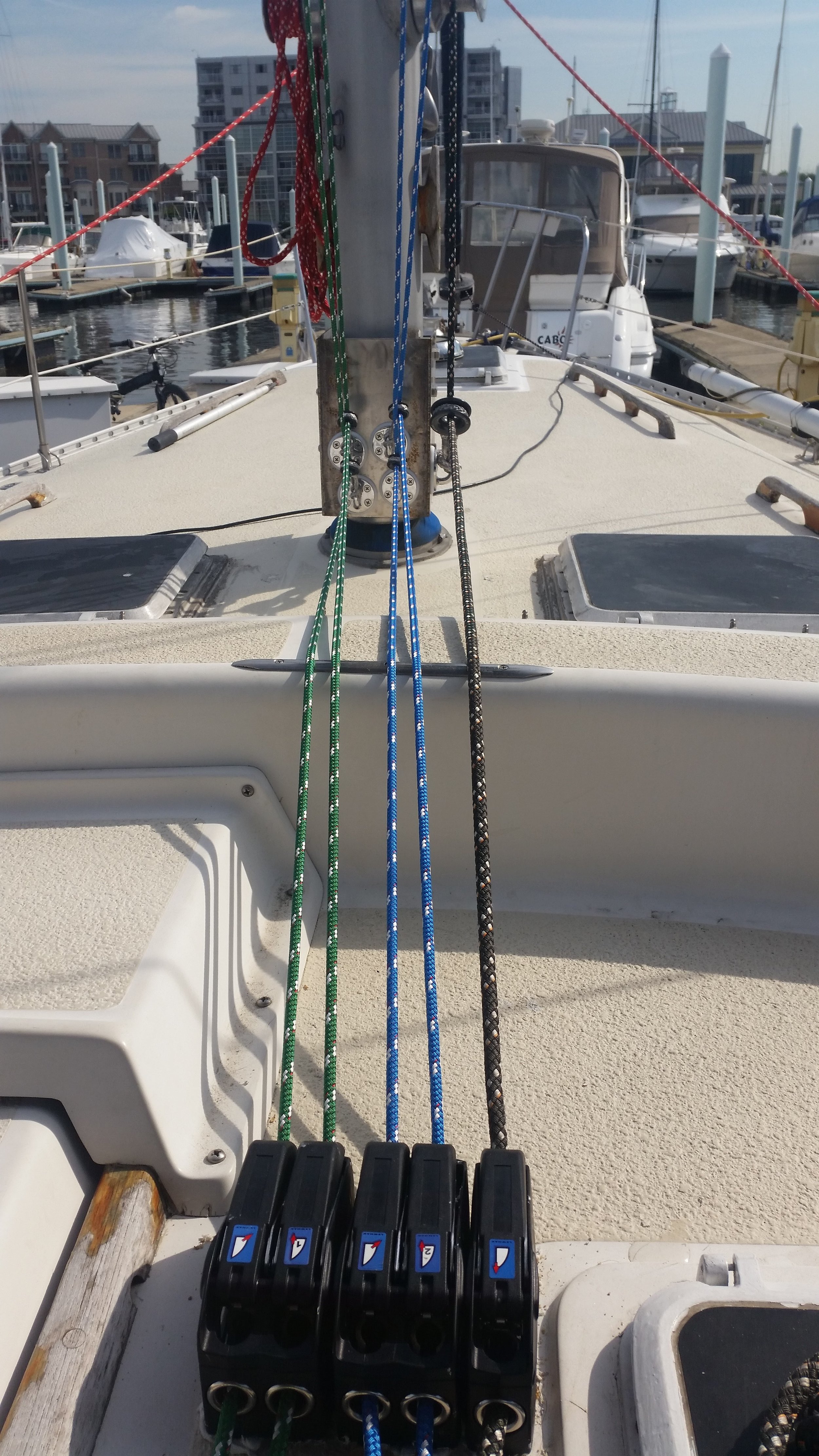
The lines should be led fair and straight from the mast to the clutch and onto the winch. Each turn and bend adds resistance, so minimizing the number of turns will reduce the effort needed to manage the sail. 

FullSizeRender.jpg

The Antal rings in Dyneema loops allow the block to position itself and move as the sail moves around above it. If the boom swings over to the side, the lines that hold the rings will move as well without question nor effort. The force from these turning blocks is all directed towards the bottom of the bracket, that way all the force is rotational instead of lateral. The four stainless steel bolts are setup to handle this sort of load with ease. 

FullSizeRender.jpg

Lastly, the system needs to work. The lines leaving the clutches need to reach the winch with as little angle as possible. The halyard is going to be under the most load, so it has priority in its placement. The tack and clew lines are set while the sail is slacked, so they can stand to be a little less perfect. I set the first reef to be in the least ideal position since that reef is only taken in when the weather is starting to turn. The second reef is set more ideal since it is taken in when the weather has gone from bad to worse. The halyard has the fairest lead of them all, reaching the winch from a beautiful angle. 

FullSizeRender.jpg

Ignoring the structural and engineering side of it, the last task for this setup is to look sharp. If the lines are running all over the place, it will begin to look haphazard. By keeping everything straight and organized, it just looks good and is easy to understand.  

At a glance, you can see that the green lines work together, and the blue lines belong together as well. The halyard runs off on the side, so it obviously works alone.  This sort of simplicity will allow anyone new to step up to the clutch bank and tuck in a reef when the time is right.

Converting to Lines Led Aft: Part 6, The Holes

Having all of your running rigging led back to the cockpit might sound like a dream come true. Imagine sailing along and the wind pipes up a bit. You reach over and lower the main halyard, crank in on the tack and clew lines and re-tighten the main halyard. All the while, you are standing right next to the helm. That's right, you are able to sheet, reef, raise and lower sail, and steer, all while standing by the helm!

As we learned from fairy tales about genies, all dreams come at a price. In the case of this dream, the price is a slew of holes drilled through your deck! 

FullSizeRender.jpg

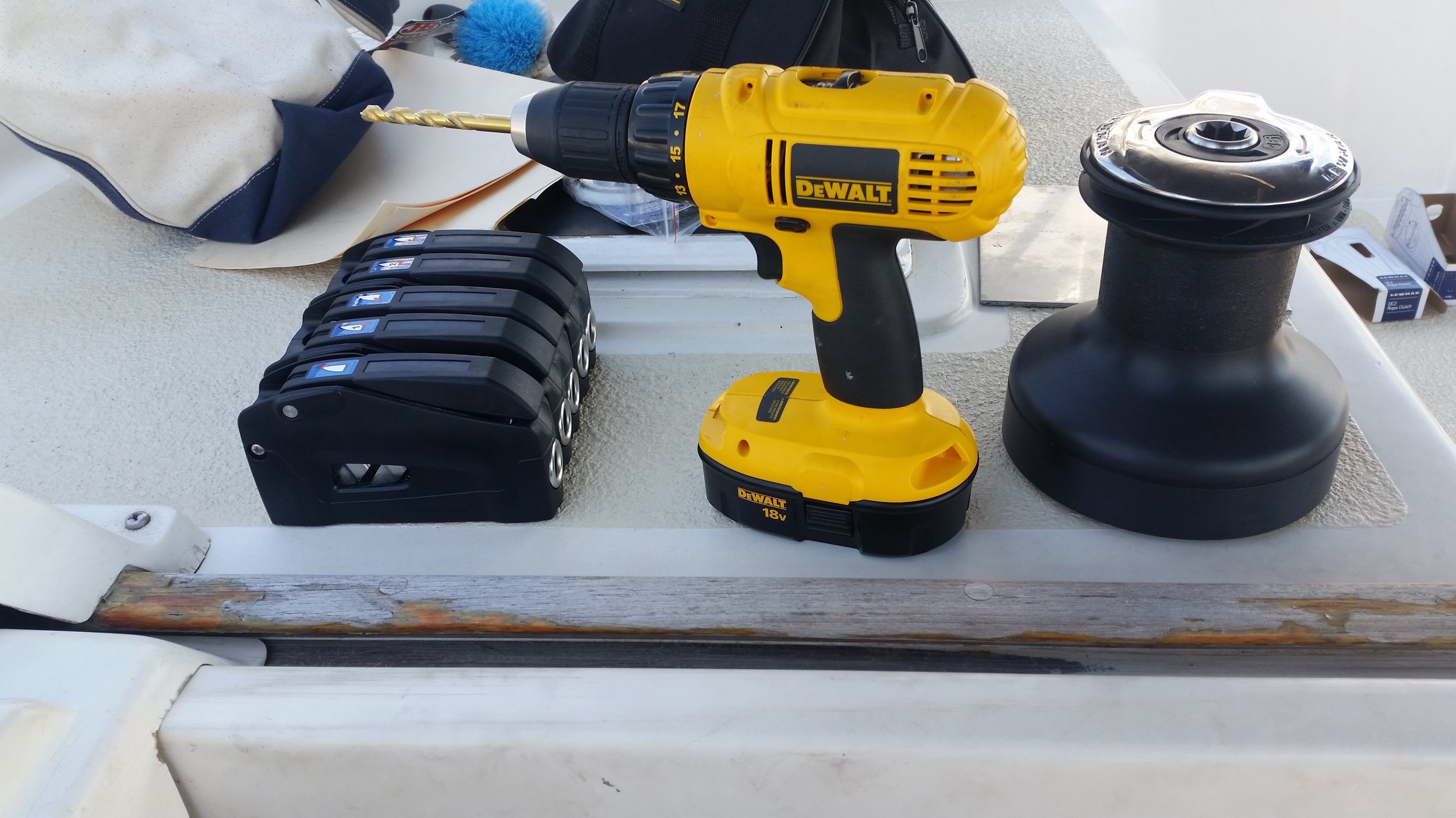
The clutches require two holes each and the winch requires another five holes! For a setup like this, we are forced to drill fifteen holes!

FullSizeRender.jpg

Each hole perforated the outer fiberglass skin, core, and inner fiberglass skin. Each hole is also a source of potential leaks that can lead to a rotten core and a soft spot in the deck. For this reason, way too much bedding compound should be used when bedding the bolts and their parts to the deck. Having bedding compound bled out the sides of the clutches and winch base might not look the cleanest, but it does guarantee you that there are no voids under the component. Voids will allow the passage of water and will hold moisture. With time, these voids will be the death of your deck and lead to costly repairs in the future.

Each one of these holes has the potential to cause serious havoc on your yachts structural integrity. The choice to have holes drilled in your deck should be made knowing the potential consequences of the convenience. The counter argument of "Do a good job and make sure that nothing bad will happen" is what we all think while planning and working. The sad thing is, if an invisible flaw occurred, its existence will go unnoticed until catastrophe occurs and rot has set in. Worse than voids while bedding hardware is time. 

Voids lead to obvious problems, time can cause new ones. A perfectly bedded item today may not be so perfect in the future. With time, the bedding compound can loose its elasticity and become brittle. When the component is exposed to a shock load, the bedding compound may snap instead of stretch. This invisible break in the seal will allow the ingress of water and all the failures associated with an improperly bedded item. This is why all hardware is removed and re-bedded during a refit, to address these issues instead of ignoring them. 

All in all, the holes are the shortest part of the job, and also the most stressful part. Each hole will perforate the deck and needs to be sealed up perfectly as if nothing ever happened. Each hole also needs to be lined up with the other holes, allowing the component to be mounted and fastened properly. If any hole is offset, the component will not fit and that hole would have been drilled in vain!