
Whoops!

So, the faying surface of the keel was not square to the keel sides. The stem however was cut into the keel set parallel to the keel sides. The result is a wonky frame in need of a change of plans.
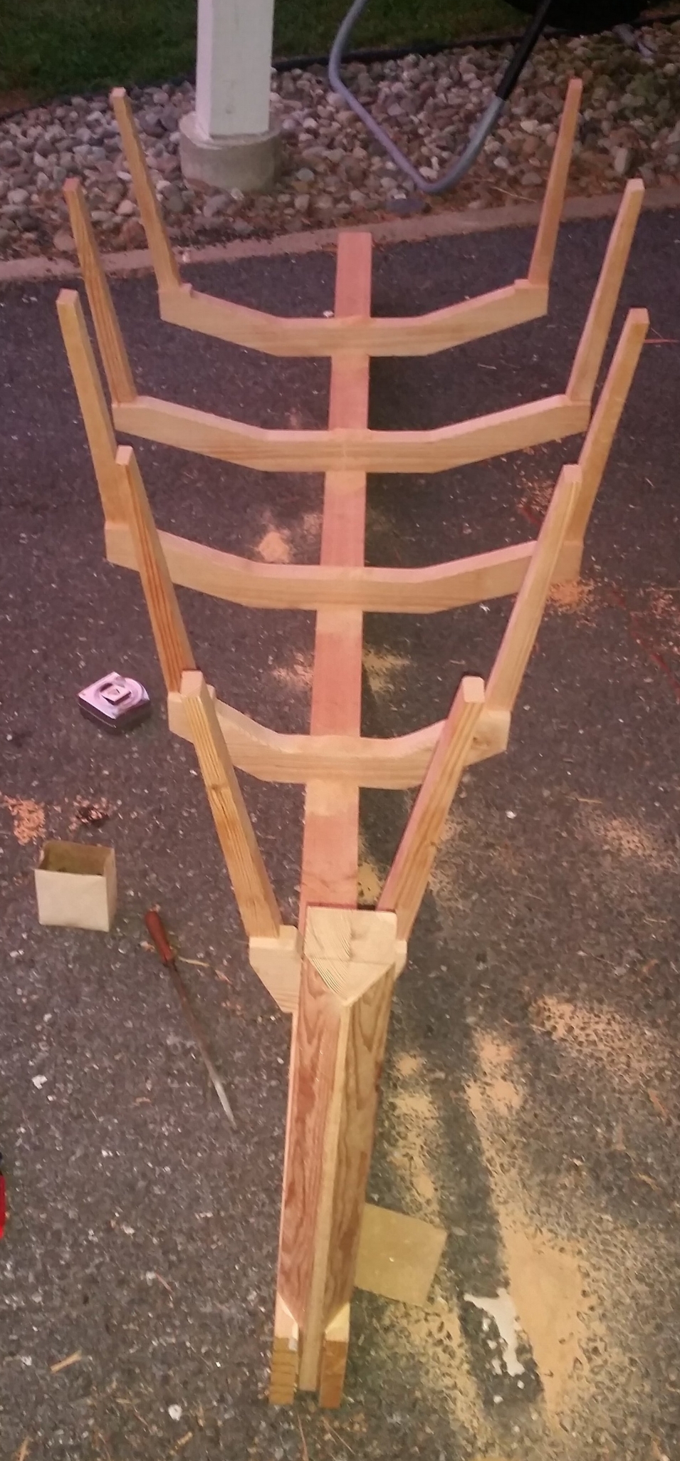
I could either cut a new stem with an offset finger that would connect into the finger joint and keep the bow plumb or I could cut the bottom of the stem off and attach the stem to the keel on the same faying surface as the frames (and inline with the frames). 

If I cut the bottom of the stem off, it would be best to set the bow at a slight angle that way the force is better transferred through the knee and with less strain on the stem. This option allows me to keep my current stem and not need to remake the stem. 

I am able to do this because the stem was cut much longer than necessary, allowing me to cut off the bottom portion and set the stem at an angle on the keel. Since the stem is being pushed back, I will need to reshape the knee to fit in front of the first floor. 

The advantage of building a dinghy is you can change your mind about things as you go, as long as you cut your timbers longer than you need. It is very easy to cut off excess, but not as easy to make members longer.

Since I will not have a finger joint anymore to support the stem, I need to wait for the bronze fasteners to arrive that I will use to connect the stem and stern post to the keel. These large 4 inch lag bolts will tie the wooden structures together and resist corrosion over the hard life of the dinghy.

Dinghy Assembly

Now that the frames are glued and screwed to the floors, it is time to assemble the backbone and frames.

The floors are fastened to the keel via bronze screws along with Titebond III to secure the floors to the keel. After everything was set and finished, I noticed that Station 4 was setup backwards on the keel! While the glue was still wet, I loosened the floor screw and rotated the floor, re-tightening it once the station was oriented properly.

To make sure the floors are set square to the keel, I rested a square along the side of the floor and the perpendicular along the length of the keel. Keeping everything square, I drove the bronze fastener all the way down, tightening the floor and squeezing the excess glue out of the interface between the faying surface of the floor and keel.

The stem was also glued in place along with the knee using no fasteners. Fasteners would interfere with later cutting and shaping that will occur in these areas, so they are forfeited for the time being. After the final shaping is completed, the stem and knee will be fastened securely using bronze fasteners.

The next steps will be to secure the stringers which will strengthen the frame up significantly and begin to transform this project from a whale skeleton into a boat!

Frame Fastening

The dinghy will be finished bright, meaning that all the wood will be varnished and oiled and no paint will be used. This means that all the small details will be visible for years to come and won't be hidden away under a coat of paint.


The floors and frames, along with their interfaces will all be visible and therefore needs to be finished in an aesthetic way. The frames and floors were all cut out and test fitted, making sure that the flare on them was appropriate. Now the sanding begins!

The frames and floors are first run on a belt sander to take off all the saw marks and pencil lines. Once the surface is smooth and flat, I transitioned over to hand sanding where I was able to round off any hard points that will project into the hull. The faying surface that will face the planking and keel was left sharp, as these areas will be adjusted later as the build process continues.

The frames and floors were lined up in the squares and pilot holes were drilled through the frames and into the floors. Bronze fasteners were also driven in to verify proper alignment and fitment.

Once everything was dry fitted and tested, it was all disassembled. The faying surfaces had a liberal amount of glue applied to them and the frames were then screwed on. Clamps were not necessary as the force from the screws provided enough clamping force squeeze out any excess glue and intimately mate the faying surfaces. Glue was also placed down the screw holes, further locking the fasteners into place.

For finishing touches, all the screw heads were oriented vertically. There is a debate about the proper orientation of the screw head, if the slot should be vertical or horizontal. The argument for vertical and against horizontal is that the horizontal slot can collect and hold water, where a vertical slot will let the water run right out.

This is very nit picky, but I chose to orient all the screws vertically. More important than the orientation of the slot is that they are all uniform. When the screw heads are all haphazardly arranged, the entire construction looks disorganized and chaotic. Orienting them all in the same direction makes everything flow better and feel more at ease. It also looks like the craftsman took the time to make sure all the details are covered. 

Excess glue was wiped away and allowed to cure. Now the floors and frames are united and ready to be mated to the keel. Construction of the dinghy is progressing quickly!

Assembling the Frames

image.jpg

The floors and frames have been cut, fitted, sanded, and fitted again. Now it is time to put them all together. I used bronze fasteners along with Titebond III wood glue. This will give the frames a strong connection to the floors. 

The outer corner of the floor/frame connection will be cut out to fit the chine log at a later point. The tops of the frames will be reinforced by the sheer clamp, gunwale, and inwale. For now, the floors and frames look like the characteristic "rib" that will support the dinghy. 

Connecting the Frames and Floors

After the frames were cut and lightly sanded, the notch was cut which will increase the strength of the connection between the frame and the floor. This notch will serve as a vertical stop while aligning the frames to their appropriate flare. 

some basic math was carried out to find the ideal placement of the notch on each frame. The height of the floor and length of the frame were added, then subtracted by 18, the final length of the assembly.if the floor was 5 inches high and the frame is 15 inches long, 2 inches would be the remainder. 

By marking the frame 2 inches high, the notch could be placed at the appropriate location to place the sheer at 18 inches. 

The use of squares and straight edges proved invaluable for this step. All the frames were frasured, marked, and identified to their corresponding floor and side.  Frames were now labeled as 4A or 3B, letting me match it back to the correct floor when the assembly would begin. 

The frames were notched 0.75 inches deep, or half their thickness. This provides me with enough material so to fasten without all the extra bulk and weight of leaving the frame whole. 

After making the two cuts or frame on the bandsaw, they were dry fitted to the floors to verify their fitment.  

image.jpg

The flare of the frames was evaluated and confirmed with two squares set opposing each other. Once everything was squared up, the sanding could continue in preparation for the assembly.