Cutting the Frames

The frames attach to the floors and provide structural support to the planks that will make up the hull of the dinghy. The frames are cut out of a larger piece of Douglas Fir with straight grain and quarter sawn annual growth rings. Care was taken to avoid any large knots in the wood while using the wood in the most efficient method possible. 

The frames will guide the planks in flaring the top sides. The chine is located two full inches inboard of the sheer, and the frames need to embody this flare. To accomplish this task, careful measurements were made on a piece of lofting paper, where the final shape of the frames could be determined.  

The top of the frames are 18 inches above the bottom of the floors, and extend 2 inches beyond the floors in an atwarthship dimension. Knowing that the floors are around 5 inches high, the frames only need to extend 13 inches upward. Some overlap was added to allow firm attachment between the frames and the floors.

15 inches of vertical height is decided to be the appropriate length for the frames. The next variable is the flare, 2 inches atwarthship. By using squares, I was able to plot the points that the frames needed to reach. Then it was simply a matter of connecting the dots. 

The base of the frame shall be 1.5 inches and taper down to 0.75 inches. The bottom of the frame is set horizontally, serving as the reference point. The top outboard side is measured 15 inches up and 2 inches out. The upper inboard point is meaured 0.75 inches in from there. With the lines drawn to connect the dots, I had a diagram of the frames, now to bring them into real life! 

image.jpg

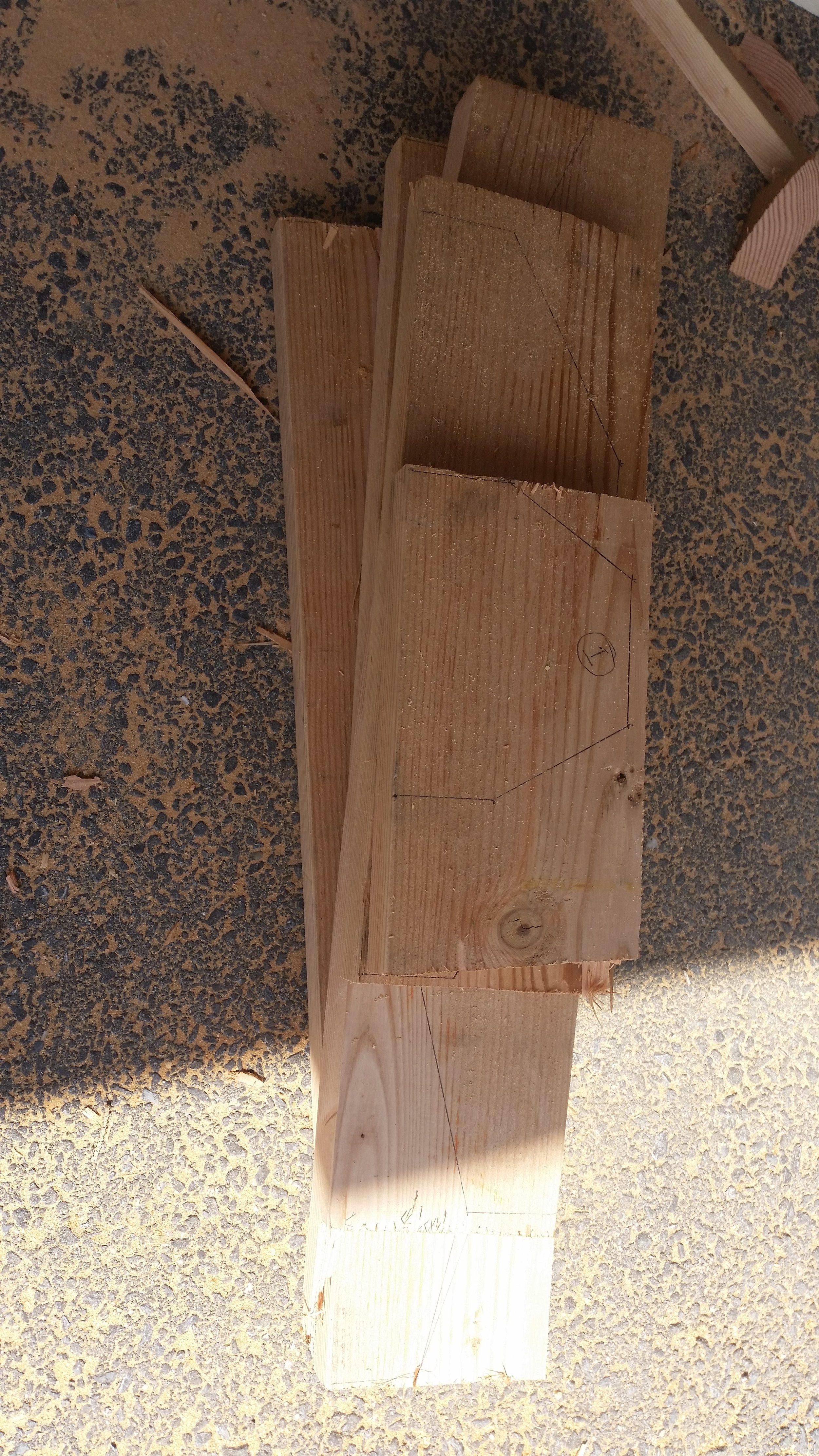
The drawing was then cut out and laid on an appropriate board. Marking the corners and connecting the marks outlined the frames, ensuring that no knots are included and as little wood is wasted. 

The frames were cut out on the bandsaw, converting the cluster of drawings into real life sticks that would become the frames of our dinghy. 
Finishing the Floors

The floors were cut out of Douglas Fir and are not the heaviest of timbers in the boat, but every bit of excess wood counts towards the total weight of the craft. Based on the scantlings for a craft this size, the floors only need to be 2.2 inches tall, and 0.7 inches wide. As you can see, these floors are greatly oversized at 5.25 inches tall and 1.5 inches wide!

I want to keep the width as that provides more wood for fasteners to drive into, but the height is a bit much. The other negative caused by the extreme height of the floors is it will greatly reduce the interior space of the dinghy. The height of the hull will be 18 inches, and a 5 inch floor would only leave us with 13 inches of interior depth. Naturally, height was on the chopping block!

I marked a line that will give me a uniform height of 2.25 inches and then cut along the line with a bandsaw. 

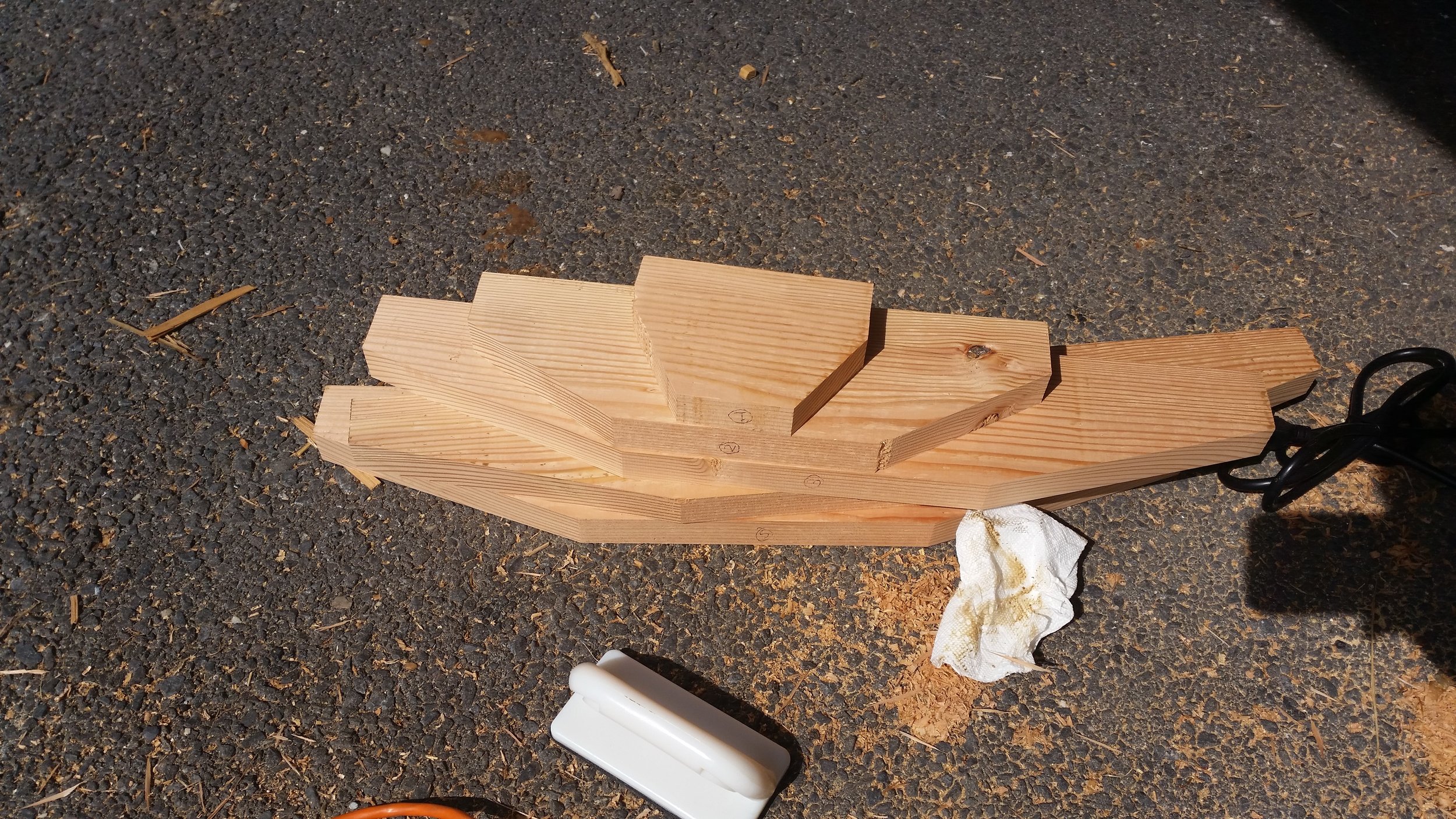
The central portion of excess wood was removed, which reduced the weight of the floors considerably without significantly impacting the strength of the floors. The weight reduction in the front floors was negligible, but quite significant in the aft floors. After sanding and fitting the frames, the setup will be ready to fasten permanently with glue and bronze screws. 

Floors

With the measurements transferred back to the backbone and verified on the deck for fitment, it is time to continue with the construction of the hull. 

The measurements from the keel were transfered to a large paper which served as lofting paper to cut out the floors. The marks were connected by way of a batten, producing a fair line that flows from bow to stern.

The floors will end at the chine and the frames will attach to them. The chine will be 2 inches inward of the gunwale, producing a curve to the hull that is pleasing to the eyes.

The floors need to follow the angle of the hull, allowing the planks to lead into the rabbet line on the keel. These points are all known, since the chine is set 3 inches higher than the rabbet, adding three inches to the floor marking and connecting the dots produced a floor template. Then the top of the floor was added to give the unit strength. Based on Herreshoff's Scantling Rules, I knew that the floors need to be 2.2 inches high, so 2.2 inches were added to height of the floors. This means that the ends where the corners taper down to nothing are too small to function. Normally, the floors would taper and come to an end, and the bottom futtock would attach to the floors, but this hull is so small that it doesn't make sense to make a floor, bottom futtock, and top futtock. 

Instead, the floors are going to extend all the way to the chine and serve as the bottom portion of the frames, with the top futtock fastened to the end of the floor/futtock.

Based on these measurements, the frames were drawn on the boards available and set to be cut out.

The bandsaw made quick work of the boards, cutting the floors basic shape out in very little time. The floors received an individual number identifying them to their corresponding station.

With the floors set on the keel, the bottom hull profile is beginning to take shape. The next step will be to fabricate the frames and connect them to the floors, making the characteristic "ribs" of the boat.

Visual Inspection

The importance of visually inspecting your equipment can not be underrated!

This battery was removed during a survey of a power boat. The owner claimed that the battery works fine, as he used it to start the generator yesterday! Turns out the generator is connected to this battery and in parallel with the engines starting batteries. When this battery died (and exploded), the owner never noticed because the generator kept starting. 

The inside of the battery is severely corroded and all the cells are dry!

"Maintenance Free" doesn't mean "Inspection Free". Even if you don't need to add water to your cells, it is still a good idea to look at your equipment periodically to make sure you don't have something like this lurking beneath your cabin sole.

Redesigning the New Dinghy

With the maximum dimensions of the dinghy measured in place on the deck, it is time to finalize the design of the dinghy.

Using a hull design program from Carlson Design, I was able to place specific stations and allow the program to produce a fair line. This program also allows me to evaluate the maximum displacement of the craft and evaluate where the center of buoyancy will lie. The program is available for free from Carlson Design.

http://carlsondesign.com/projects/hull-designer/

Follow the link above to the webpage where the calculator can be found and downloaded.

Clicking the link below the yellow arrow will download the file which can be opened to run the program. The program works wonderfully, and provides a wealth of information in just moments. 

With the maximum and minimum measurements, I was able to design a dinghy that fit within these tolerances. I then received approval from Maddie and got the go-ahead to build such a dinghy.

The measurements were then transferred back onto the dinghy and verified on the deck, making sure that the chimney will not be obstructed and that the hatch will be fully covered.