Bedding Hardware

Whenever you make a hole in your deck, you need to seal it to avoid water intrusion. This is easy enough when you are repairing a hole in the deck with wood or fiberglass, but what about when you install hardware through the deck?

This is where bedding compound comes into play! Bedding compound will seal up any voids that may exist between the item and the deck. This seals out water and moisture, while adhering the item to the deck. Bedding compound also needs to be forgiving, allowing it to stretch and wiggle as the boat twists through the waves and expands during the heat of the day. 

My preferred bedding compound for marine hardware is 4200, manufactured by 3M. While not as popular as 5200, 4200 does an excellent job and is much more forgiving. 5200 is considered a "permanent" adhesive. When 3M (a company famous for making things that stick) says its product is permanent, they mean it! I have seem the top layer of a deck be ripped up with deck hardware that was bedded with 5200. 

4200, on the other hand is just a hare's breath less "permanent" than 5200. This means that it will still seal out all traces of water and firmly adhere the fitting to the deck, but it can be removed with enough persuasion in the future. 

I like retrieve-ability in everything I do. The thought that something is now permanently installed and can never be removed irks me! Whether it be an implant crown that I place in my dental office or a chainplate, I want to have a method to remove it should the situation arise. 

When you use bedding compound, the concept is simple: You want to fill all the voids so that it occupies all the space between the fitting and the deck. To ensure that you have enough compound in there, you need it to squeeze out. Bedding compound is very gooey and is rather hard to clean up; but if you follow a few easy steps, cleanup could be much easier.

In this example, we will be bedding chainplates. The first step is to cover everything you don't want bedding on with tape. Then trim off all the excess tape with a sharp knife. 

Next set the plate over the chainplate on the hull and outline it with tape as well.
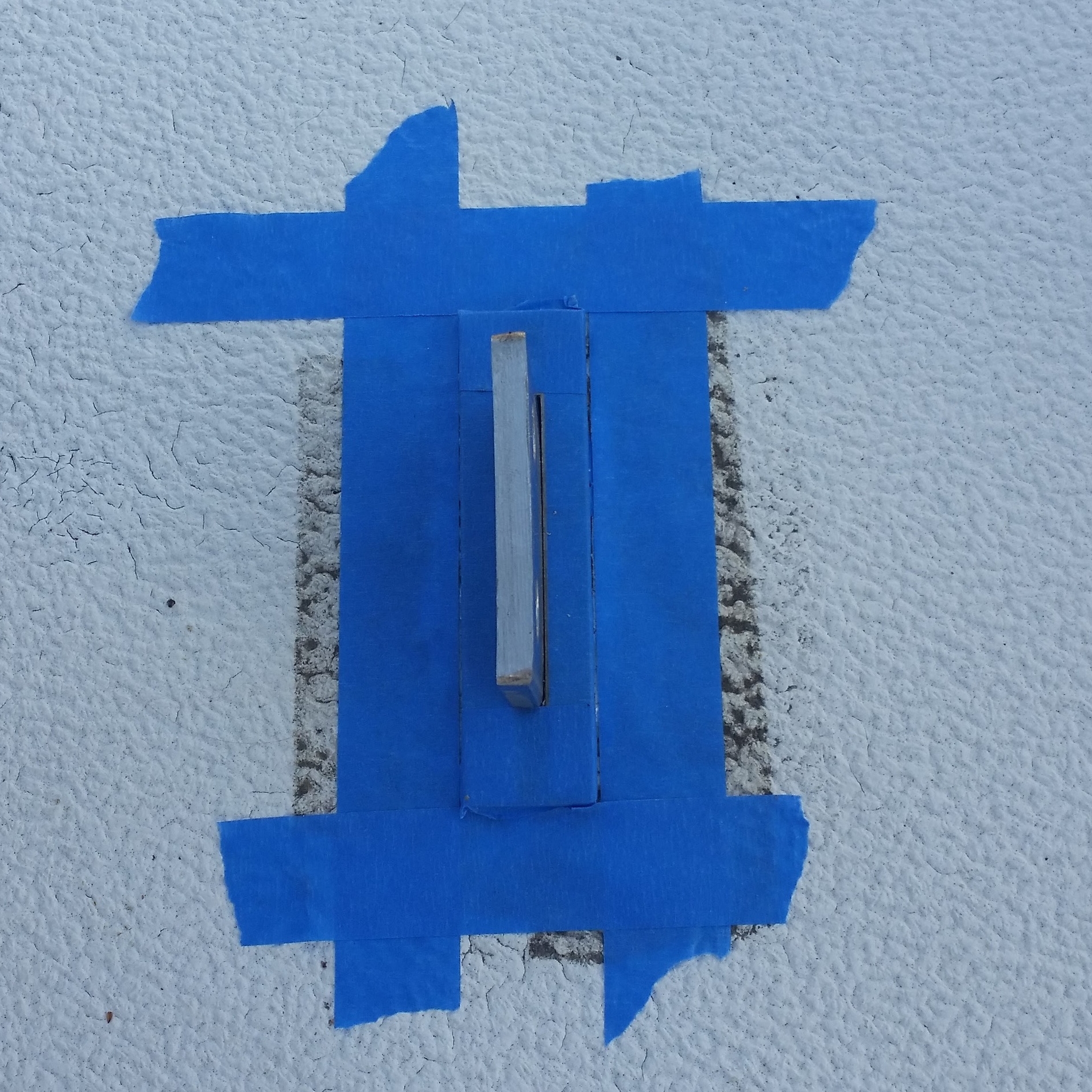
When you load up the space around the chainplate with 4200, be sure to get some into the  screw holes as well. 
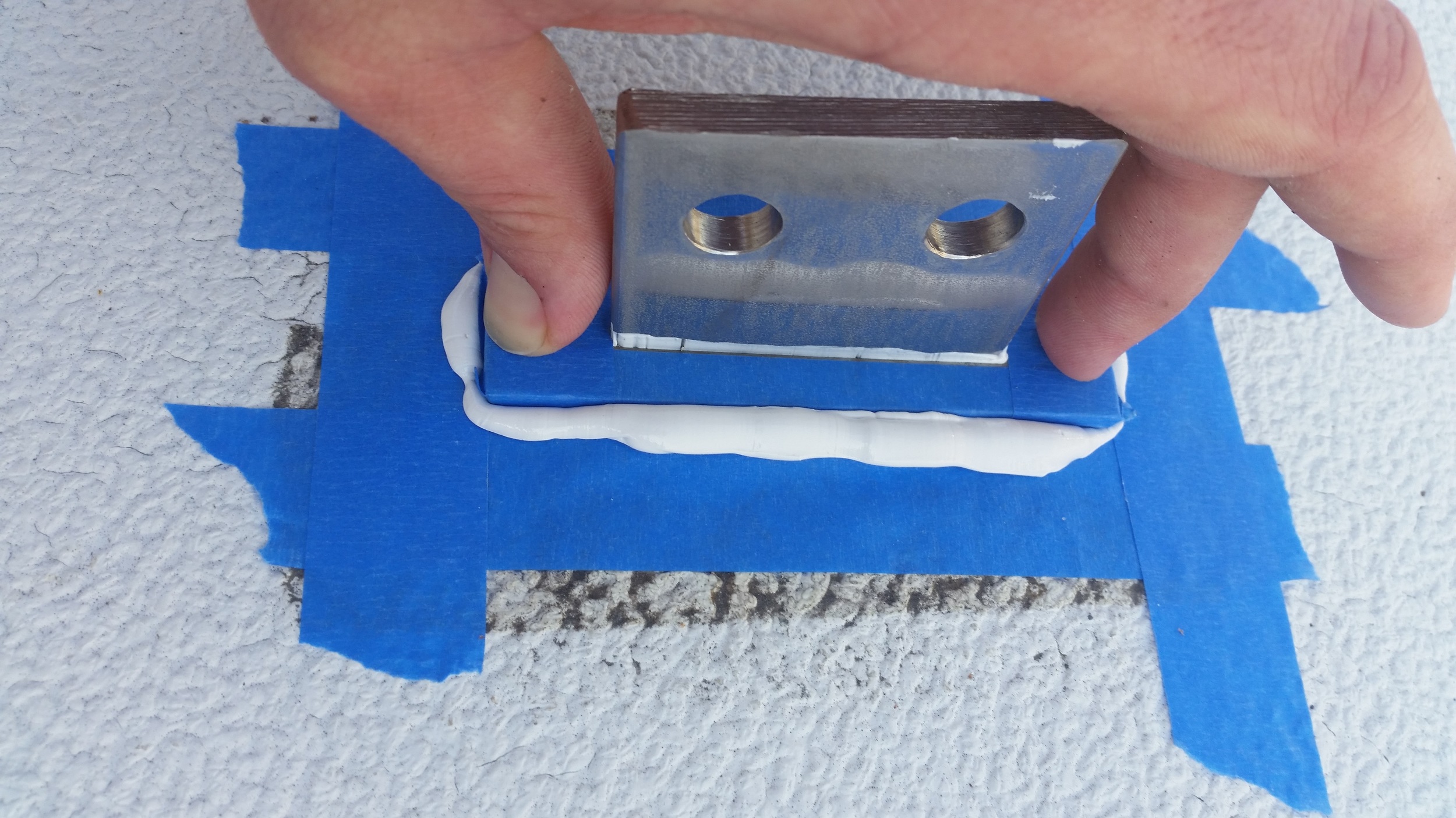
As you push down on the cover plate, you will see the excess ooze out of the space and onto the tape. You want to see excess ooze out of all the sides. If one area didn't ooze any, it means that there wasn't enough bedding compound in that area and it might be dry. It is strongly recommended to pull the fitting off and add extra compound to the lacking areas, although this will be very messy! This is why it is best to load it up with way more than you think it will need that way you only have to do this step once.

Once the excess has oozed out, simply peel the tape up and the majority of the excess will come off with it. Any extra squeeze out can be wiped off with a paper towel. 

Be sure you see some squeezing out between the cover plate and the chainplate. Many people will focus on sealing the edges of the cover plate but forget to seal along the chainplate, resulting in a leaky deck that will rot out the deck core!

This is an easy process to do, it just takes some time and patience to get it done right.

Galvanic Corrosion

When inspecting your spars, pay special attention to any fittings attached to the spars. Most spars these days are made of aluminum while the fittings are made of stainless steel. The dissimilar metals will lead to galvanic corrosion of the aluminum spar. 

While it is impossible to see under or inside a fitting connection, there are some clues that can alert you to an internal compromises. Galvanic corrosion will cause bubbles to appear around the fittings under the paint. 

Source: http://www.boatus.com/seaworthy/rigging/BUBBLES.jpg

Source: http://www.boatus.com/seaworthy/rigging/BUBBLES.jpg

When you look at your fittings, check to see if the paint is beginning to bubble. If you see bubbles, you need to address this area before the problem gets any worse! 

Another sign of corrosion is white dust emerging from your fittings. This dust is aluminum oxide, usually resulting from galvanic corrosion with stainless steel fittings. 

To avoid these issues, be sure to isolate the two metals. Plastic separators can be placed between the stainless steel and aluminum fittings and lanocote can be placed on the sides of screws and rivets to isolate them as well.

When you evaluate your rigging, take a close look at all fittings and make sure everything looks clean and perfect! Peeling paint is a preliminary sign that something might not be isolated.

Magnus Hitch

The Magnus Hitch is a handy knot that I use to tie fenders to lifelines and rails. This knot is easy to tie, holds well, and is also easy to untie. The knot is very similar to a rolling hitch but the standing part and the tail exit on the same side of the knot. This knot can also be used to tie a hitch onto another line as it will not twist and distort as much as a rolling hitch would. 

If you need to tie a very secure hitch, the icicle hitch will out hold a magnus hitch, but the magnus hitch is much easier and quicker to tie. 

The reason I prefer the magnus hitch over the rolling hitch for securing fenders is both tails come off in the same direction, making a cleaner appearance on the rail or lifeline. The other advantage is the magnus hitch makes adjusting the length of the fender whip very easy!


We will go over the very easy steps to tie the Magnus Hitch.


Simply pass the working end through the ring


Pass the working end through the ring again, making two round turns on the ring in the same direction. If the knot is going to be loaded and pulled on, the turns would go in the opposite direction of the load; this will keep the knot from slipping on the line it is hitched to.


Now pass the working end over the standing part.


Pass the working end under the ring


Now pull the working end through the loop and tighten the knot.


The finished knot will have the standing end and working end both exiting parallel to each other. If you need to adjust the length of the fender whip, simply work the length of line through the knot and re-tighten.

Installing the Ridge Beam

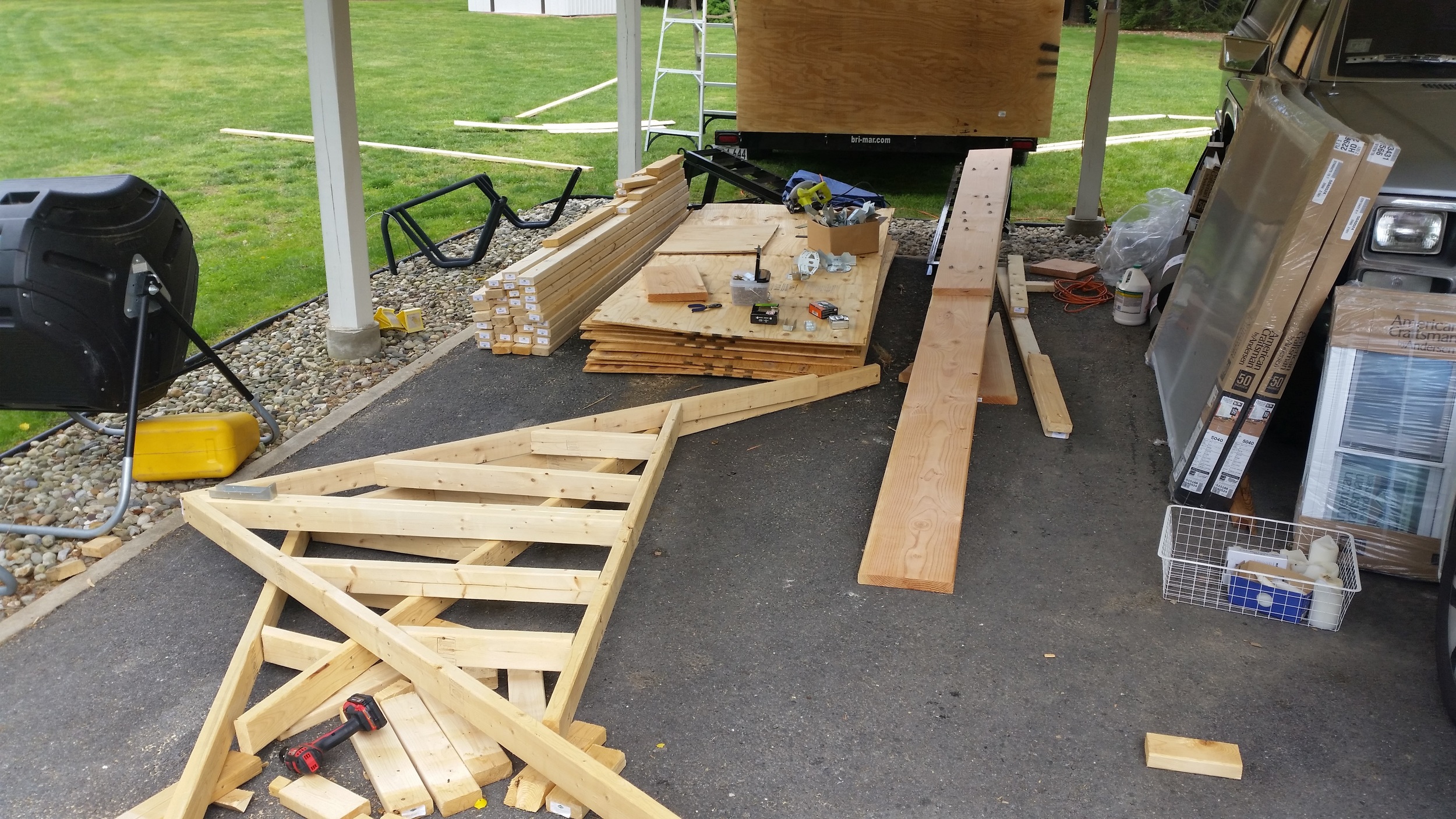
The ridge beam is a massive piece of douglas fir weighing 130 pounds and measuring 18 feet long. I am not a home builder, so I designed this tiny house using boat building rules. If the house were flipped over, this beam would become the keel and it is sized accordingly. My rational is when heavy snow piles up on the roof, this ridge beam is going to have to bear the weight of it all and must be built to withstand the hypothetical task.

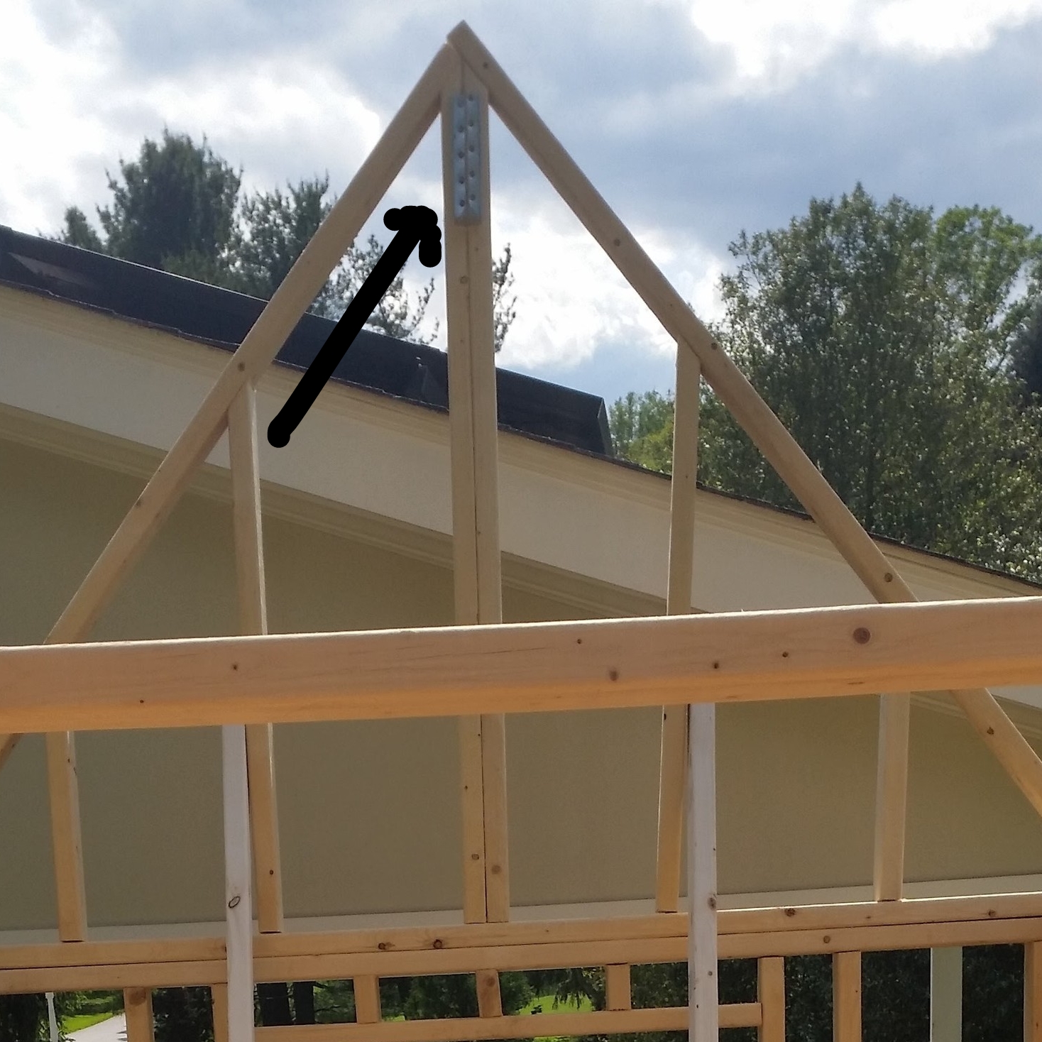
The ridge beam is going to rest in small metal channels that are set at the top of the trusses. These metal strong-ties will securely connect the end of the beam to the truss.

The only problem with our plan is we had to raise 130 pounds of 18 foot ridge beam 13 feet into the air. Rigging to the rescue!

The beam was carried into the tiny house via the back window on its side. It was fed into the house at an angle with the forward end passing over a temporary support to the frame walls. Additional 2x4s were placed across the frames to help support the beam. This gave us a very strong point to rest the beam on and if the beam fell, it would only go as far as the wood cross members.

Strong screws were used as blocks to guide a rope to make a pulley system. Two screws were set into the truss, one on each side of the peak, and a third screw was set on the underside of the ridge beam to keep the rope from slipping off.

A rope was securely tied to the trailer to provide an anchor point, over the truss, under the beam, back over the truss, and out to my mom who was manning the ropes. This assembly was tied on both ends so that as we (my dad and I) heaved the beam up, my mom could take out the slack in the line. This provided enough purchase for her to comfortably hold the beam in the air while we rested. We would heave up a few inches, then she would take up the slack, and we would rest; then repeat!

The screws and wood edges offered too much resistance to pull the assembly up by the pulley system, so it was relegated to holding the beam up and taking out the slack. We raised the single width section first and positioned it into the strong tie at the top of the truss and a lashing was tied to the beam to keep it attached to the truss while we focused on the other end of the beam.

The very heavy end (with the scarf joint and butt blocks) needed to be raised above the truss and lowered into the strong-tie channel to fully secure it. This came down to brute force as there was no nice way to rig a pulley system to hoist the beam into the place. I bit the bullet and lifted the very heavy beam high up and carefully into position. Then the ends were secured with screws to hold it in place!

Due to the extreme weight aloft, we had set up wooden stays inside the structure which were tied together and to the floor. We were very happy these were in place when that weight loaded the walls. If we were building on a level surface, they might not be needed. Being how we are building on a slight incline, the whole structure is leaning back. All of that weight up there would easily rip the trusses out and send the upper structure crashing down!

Now that the ridge beam is installed, it's time to start adding the rafters.

Edson Bilge Pump Rebuild

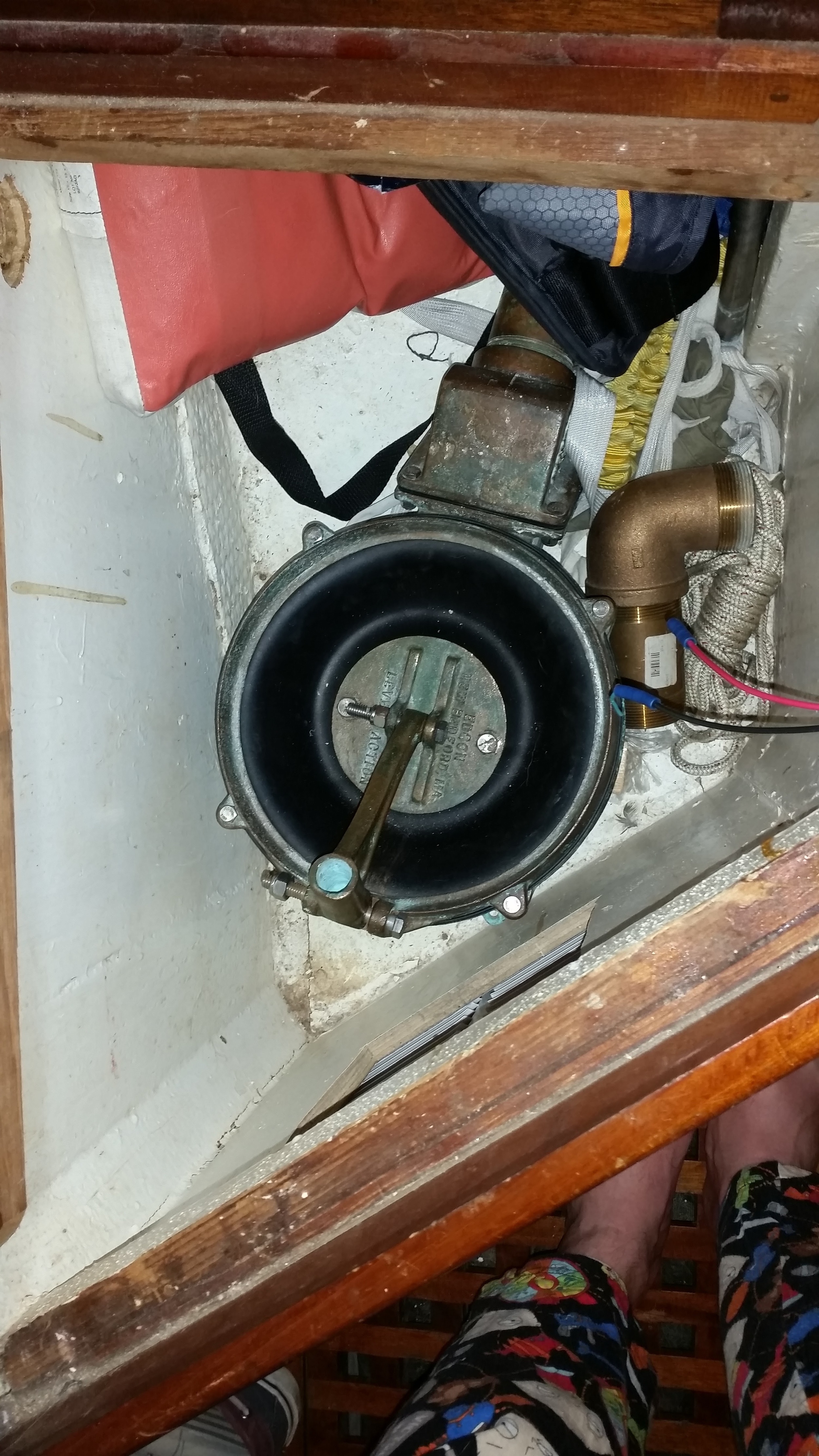
The new diaphragm and flapper valves arrived from Edson, allowing me to finish the rebuild of this old bronze Edson pump. Now that I know how far the pump lever needs to move, I can finalize its placement in the boat.

This pump is capable of pumping 1 gallon per stroke, which means that we can easily pump a lot of water without depending on our batteries holding up in the event of an emergency. By mounting it inside the cabin, we are also able to pump from the safety of a closed cabin if the situation were to call for it.

On a less "gloom and doom" viewpoint, this pump will make cleaning the bilge that much easier since I can keep an eye on the water in the bilge while pumping it overboard at the same time. My current manual pump is located in the cockpit, which doesn't let me keep an eye on the water clarity as I clean the bilge. As soon as the bilge water is clear, I can shut the hose off and dry out the bilge! This can make the quick and easy process of cleaning the dust out of the bilge all the easier.

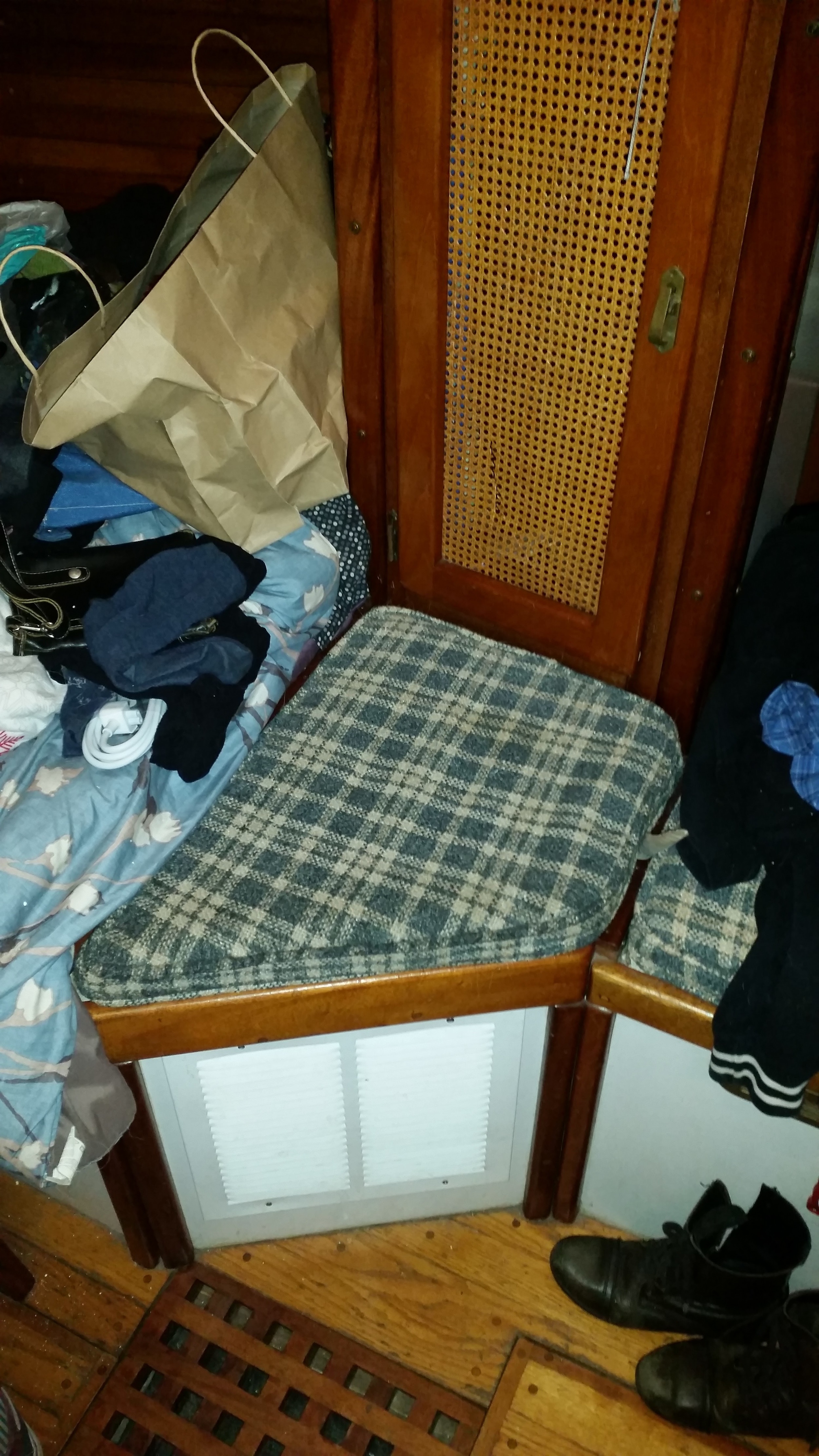
The downside to this bilge pump is its size. This thing is huge and finding a place that is both out of the way and accessible that can fit this behemoth has proven difficult. The locker where I used to keep my dive gear seems like a good spot for the pump

The bilge pump fits in the bottom of the locker and can be plumbed with with relatively short hoses. This will keep down the amount of head and resistance on the pump and increase its efficiency.

I do need to build a base for the pump so that it can mount on a level surface with the hoses attaching to it.

The plan for routing the hoses is to lead the intake hose from the bilge under the quarter berth and through the bulkhead into the locker. From there it will enter the bottom of the pump and exit into the back of the locker where it can run up the side of the hull and exit through a (yet to be installed) 2" through hull fitting just under the rubrail. A seacock will be mounted on the through hull fitting to avoid water flowing back into the boat when heeled over or if the hose were to leak. 

This bilge pump will hopefully only be used to clean the bilge, but if we did need to use it in an emergency, we can do it from the comfort and safety of the cabin.