Installing the Ridge Beam

The ridge beam is a massive piece of douglas fir weighing 130 pounds and measuring 18 feet long. I am not a home builder, so I designed this tiny house using boat building rules. If the house were flipped over, this beam would become the keel and it is sized accordingly. My rational is when heavy snow piles up on the roof, this ridge beam is going to have to bear the weight of it all and must be built to withstand the hypothetical task.
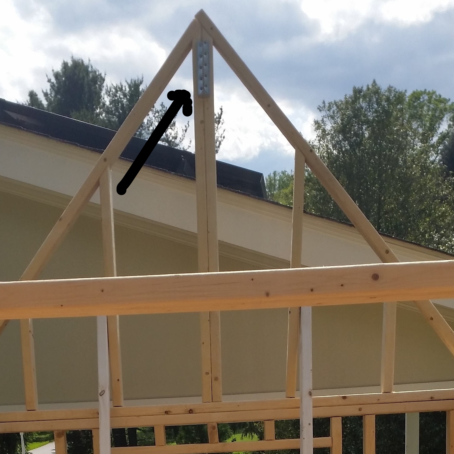
The ridge beam is going to rest in small metal channels that are set at the top of the trusses. These metal strong-ties will securely connect the end of the beam to the truss.

The only problem with our plan is we had to raise 130 pounds of 18 foot ridge beam 13 feet into the air. Rigging to the rescue!
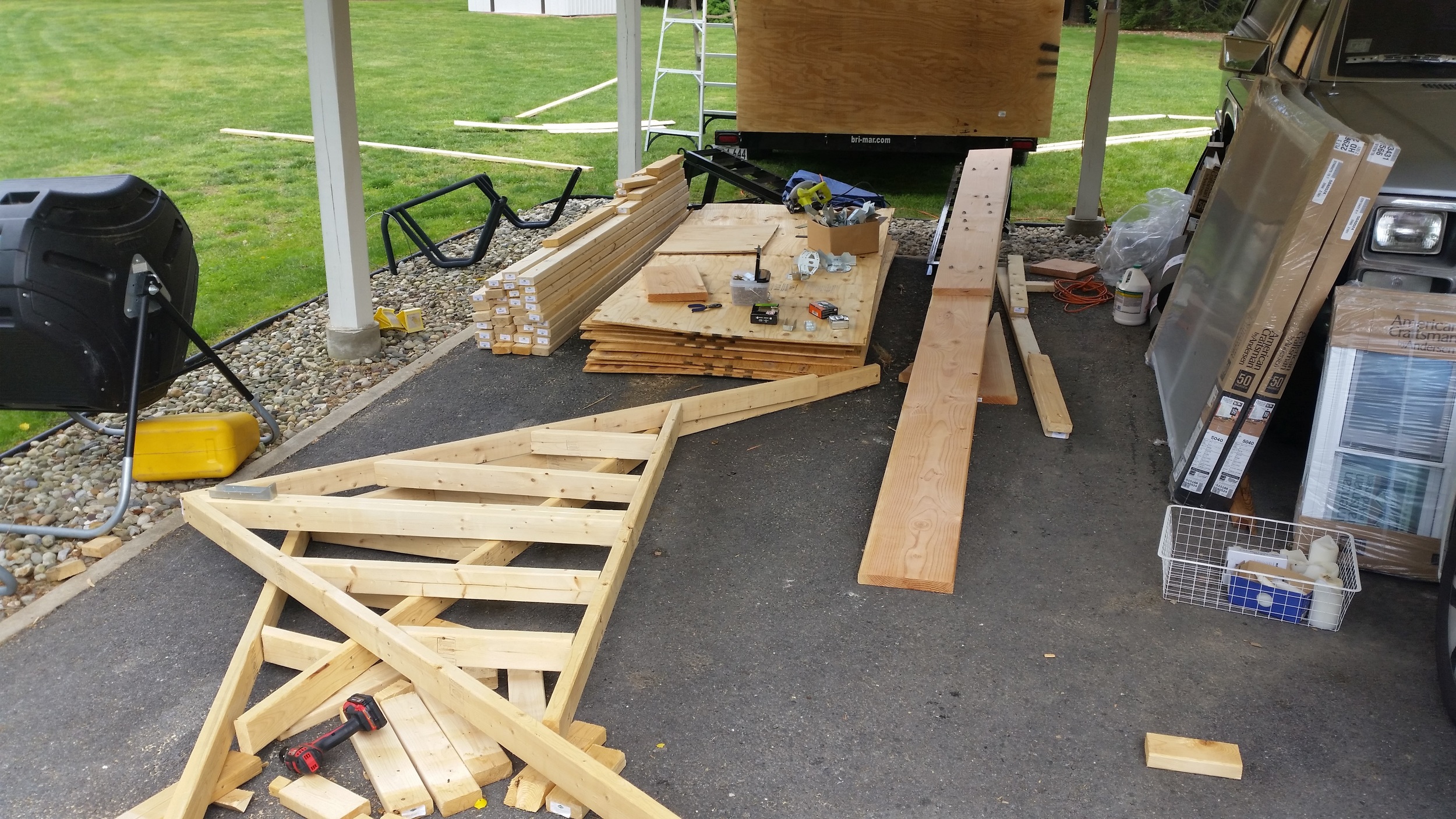
The beam was carried into the tiny house via the back window on its side. It was fed into the house at an angle with the forward end passing over a temporary support to the frame walls. Additional 2x4s were placed across the frames to help support the beam. This gave us a very strong point to rest the beam on and if the beam fell, it would only go as far as the wood cross members.

Strong screws were used as blocks to guide a rope to make a pulley system. Two screws were set into the truss, one on each side of the peak, and a third screw was set on the underside of the ridge beam to keep the rope from slipping off.

A rope was securely tied to the trailer to provide an anchor point, over the truss, under the beam, back over the truss, and out to my mom who was manning the ropes. This assembly was tied on both ends so that as we (my dad and I) heaved the beam up, my mom could take out the slack in the line. This provided enough purchase for her to comfortably hold the beam in the air while we rested. We would heave up a few inches, then she would take up the slack, and we would rest; then repeat!

The screws and wood edges offered too much resistance to pull the assembly up by the pulley system, so it was relegated to holding the beam up and taking out the slack. We raised the single width section first and positioned it into the strong tie at the top of the truss and a lashing was tied to the beam to keep it attached to the truss while we focused on the other end of the beam.

The very heavy end (with the scarf joint and butt blocks) needed to be raised above the truss and lowered into the strong-tie channel to fully secure it. This came down to brute force as there was no nice way to rig a pulley system to hoist the beam into the place. I bit the bullet and lifted the very heavy beam high up and carefully into position. Then the ends were secured with screws to hold it in place!

Due to the extreme weight aloft, we had set up wooden stays inside the structure which were tied together and to the floor. We were very happy these were in place when that weight loaded the walls. If we were building on a level surface, they might not be needed. Being how we are building on a slight incline, the whole structure is leaning back. All of that weight up there would easily rip the trusses out and send the upper structure crashing down!

Now that the ridge beam is installed, it's time to start adding the rafters.
Edson Bilge Pump Rebuild

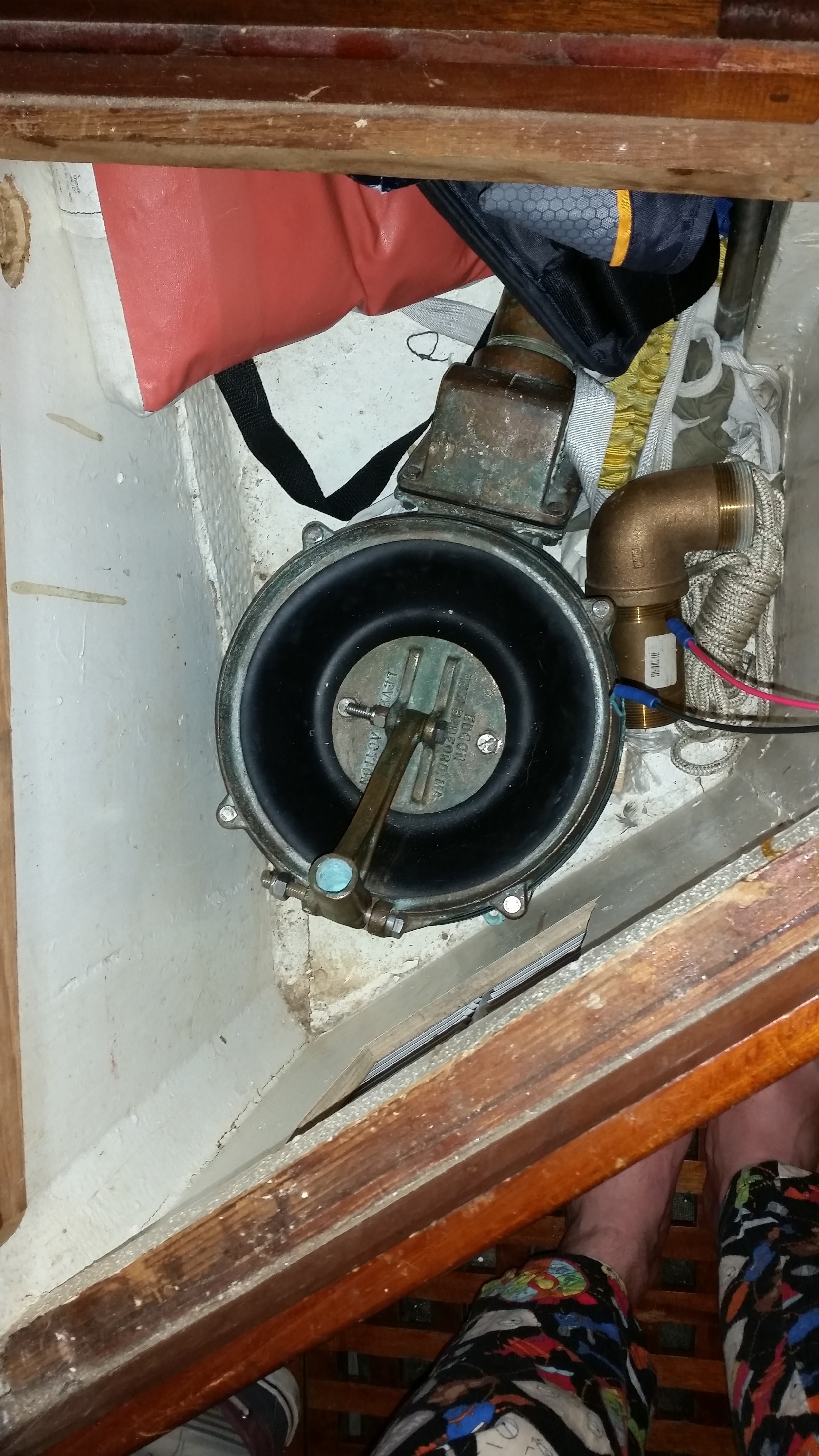
The new diaphragm and flapper valves arrived from Edson, allowing me to finish the rebuild of this old bronze Edson pump. Now that I know how far the pump lever needs to move, I can finalize its placement in the boat.

This pump is capable of pumping 1 gallon per stroke, which means that we can easily pump a lot of water without depending on our batteries holding up in the event of an emergency. By mounting it inside the cabin, we are also able to pump from the safety of a closed cabin if the situation were to call for it.

On a less "gloom and doom" viewpoint, this pump will make cleaning the bilge that much easier since I can keep an eye on the water in the bilge while pumping it overboard at the same time. My current manual pump is located in the cockpit, which doesn't let me keep an eye on the water clarity as I clean the bilge. As soon as the bilge water is clear, I can shut the hose off and dry out the bilge! This can make the quick and easy process of cleaning the dust out of the bilge all the easier.

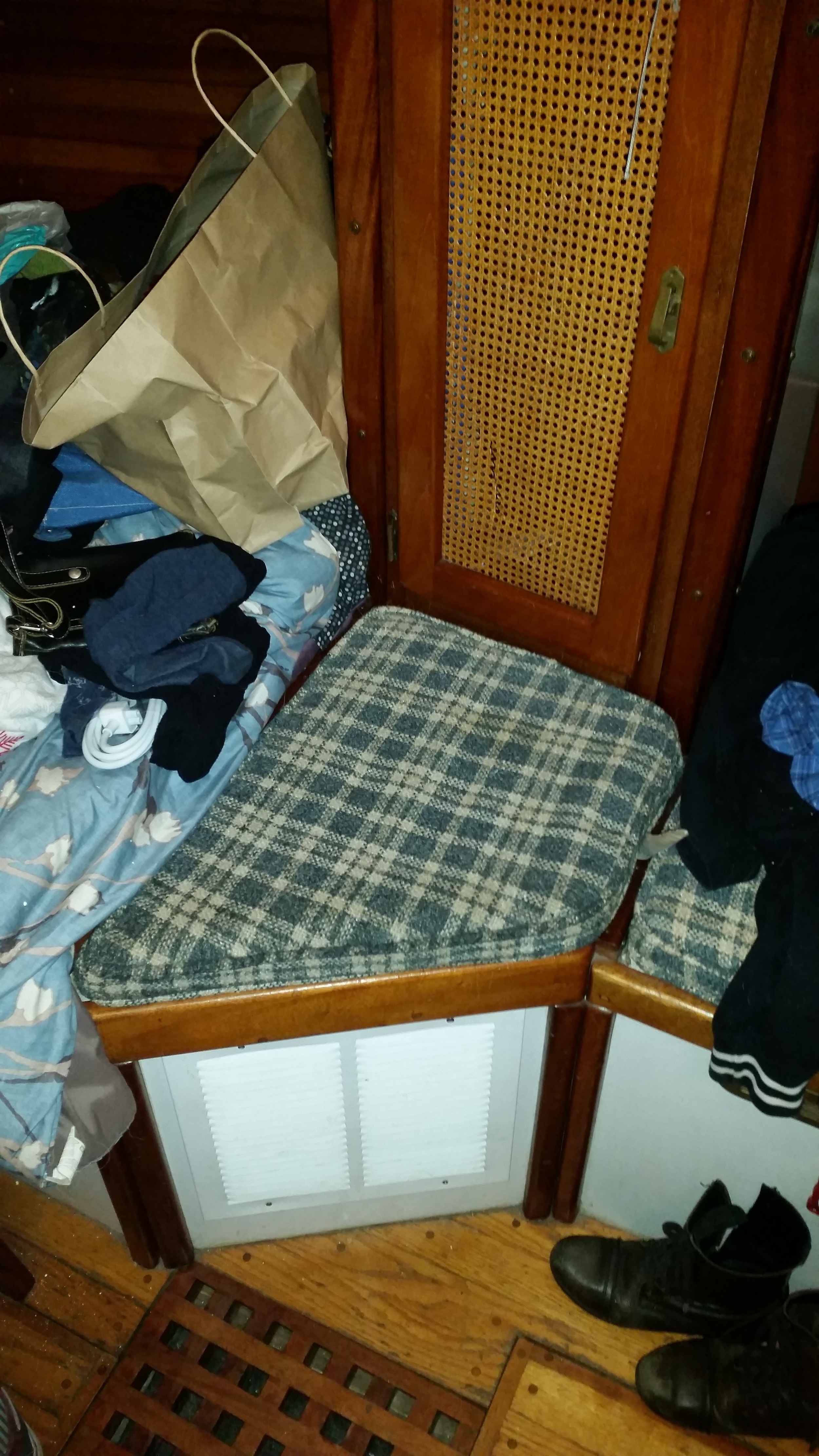
The downside to this bilge pump is its size. This thing is huge and finding a place that is both out of the way and accessible that can fit this behemoth has proven difficult. The locker where I used to keep my dive gear seems like a good spot for the pump

The bilge pump fits in the bottom of the locker and can be plumbed with with relatively short hoses. This will keep down the amount of head and resistance on the pump and increase its efficiency.

I do need to build a base for the pump so that it can mount on a level surface with the hoses attaching to it.

The plan for routing the hoses is to lead the intake hose from the bilge under the quarter berth and through the bulkhead into the locker. From there it will enter the bottom of the pump and exit into the back of the locker where it can run up the side of the hull and exit through a (yet to be installed) 2" through hull fitting just under the rubrail. A seacock will be mounted on the through hull fitting to avoid water flowing back into the boat when heeled over or if the hose were to leak. 

This bilge pump will hopefully only be used to clean the bilge, but if we did need to use it in an emergency, we can do it from the comfort and safety of the cabin.

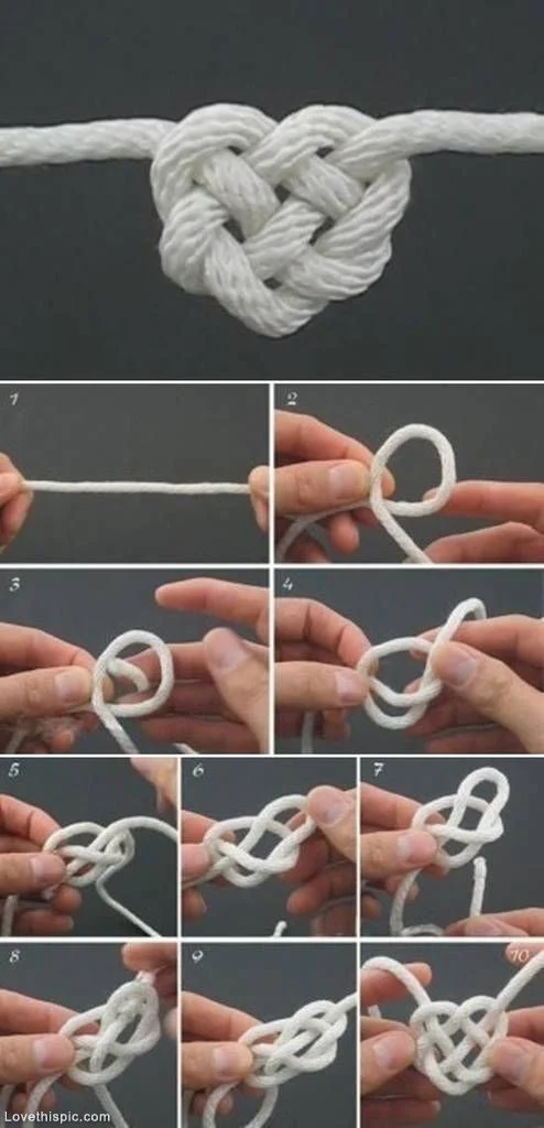
Pintrest Heart Knot

Source: https://www.pinterest.com/pin/382735668310926761/

Source: https://www.pinterest.com/pin/382735668310926761/

I have been asked to tie the heart knot seen on Pintrest and it didn't come out exactly like the picture. The apex of the heart knot is not pointy at all as it is demonstrated in the picture, but otherwise it looks close enough.

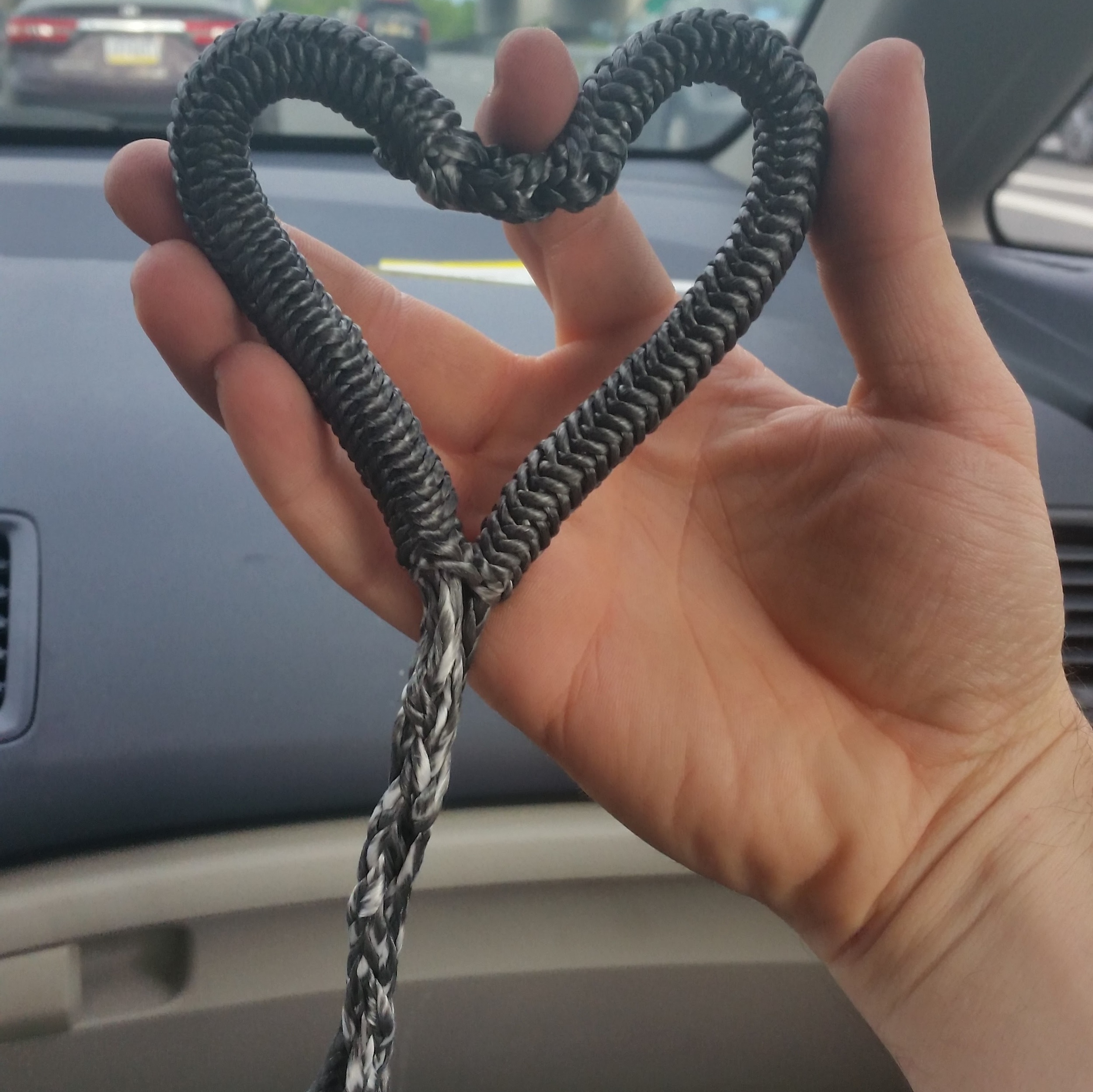
A much easier way to tie a heart shaped knot is to splice the line like if you were making a grommet.

This heart shaped knot even has heartstrings to pull on!

Clevis Pin and Cotter Pin Orientation

When performing a rig inspection, one of the most often overlooked areas are the clevis pins and cotter pins. While some people may think of these as regular metal connectors, they are actually much more than that!

Clevis pins are metal cylinders that are made of stainless steel and fit into a hole that is a specific diameter in relation to the pin. The pin and hole are such a close fit that the sheer forces on the pin are evenly distributed and the whole assembly is incredibly strong. If you placed a smaller clevis pin in the hole, the pin would deform and break at a relatively low load, simply because the pin was being point loaded by the sides of the over sized hole.

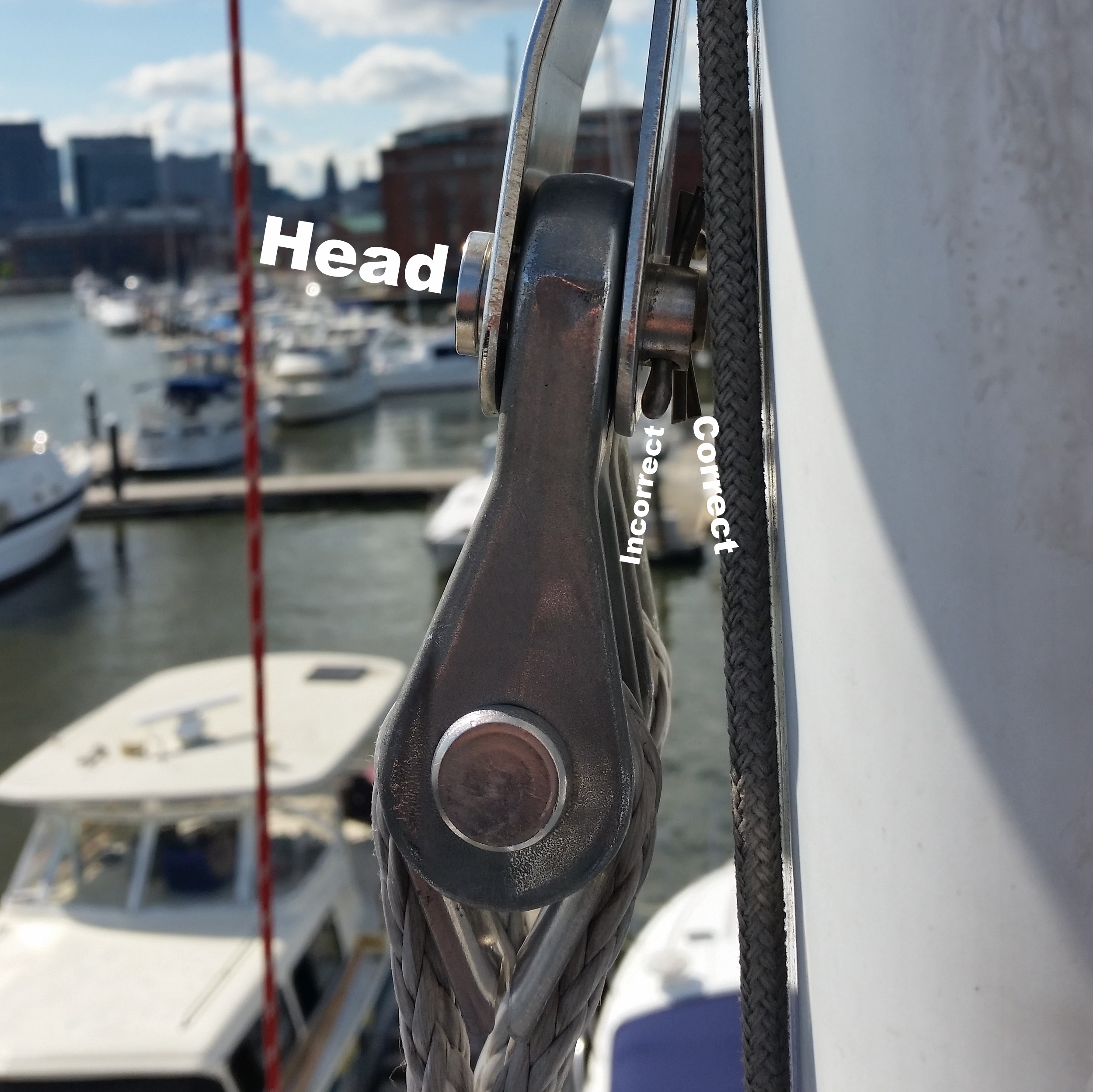
Clevis pins have a head on one end and a hole on the other end for the cotter pin to retain the whole assembly in place. When a clevis pin is installed, it should always be installed so that the head of the pin is higher than the retaining side. 

Secondly, the cotter pin should always be oriented so that the head faces up and the legs face down. The legs should be splayed around 10 to 15 degrees to ensure the pin will not fall out while trying to avoid stressing the metal legs. When the legs are over-bent, they can snap off, making it easier for the pin to fall out.

The reasons for the clevis and cotter pin orientation may seem nit-picky, but they make perfect sense when you factor gravity into the situation. Orienting the clevis pin head up, and the cotter pin head up provides many levels of safety to prevent the stay from coming disconnected.

  1. If the leg on the cotter pin breaks, it will be held in place due to gravity until it is found during an inspection and replaced.
  2. If the clevis pin rotates and the cotter pin is now upside-down; and a cotter pin leg breaks off and the cotter pin falls out or the cotter pin legs are not open enough and the cotter pin slips out: the clevis pin will still be held in place by gravity.

If the clevis pin were placed with the head down, it could easily fall out if the cotter pin were to fail. Orienting the pins with their heads up simply adds more levels of safety to the system, making the connections more forgiving in the event of a failure.

In lieu of cotter pins, ring pins can be placed to secure a clevis pin in areas where there is enough space or where the risk of fouling the cotter pin legs is high. Check stays and running back stays. are typically connected with a ring pin to avoid snagging the headsail if it rubs over the side of the mast. Lowers typically use cotter pins because it is nearly impossible to fit a ring pin between the two stays. Orienting the clevis pins so the cotter pins face each other protects the legs from snagging and fouling any lines or sails. This keeps them safely tucked out of the way, yet easy to service and inspect.

Next time you look over your rigging, be sure to take a close look at the clevis and cotter pins!

Installing the Trusses

The bottom portion of the tiny house has now been sheathed in 1/2 inch plywood and it is time to install the trusses! The sides of the trusses have not been cut, making the rafters a full 8 feet long. This may seem extreme, but with our limited crew, the long rafters helped get the truss on top of the wall frame.

The truss raised and one edge of the rafter was set on top of the wall frame. I guided the edge of the rafter along the edge of the wall frame as my dad walked the truss towards the structure. This effectively raised the truss onto the wall using its framing as a ramp system. Once the truss was on the wall frame, it was securely screwed into place.

The truss replaces the long board that was originally used to square the wall frames. Now that the plywood sheathing is in place, they are no longer needed. 

The trusses are raised, but we were concerned that they may fall over since they are only screwed on at their base. To fully secure them, we set stays inside the structure, nailed to the vertical sections of the trusses and set against cleats nailed to the subfloor. The stays were then connected via a horizontal member which tied the whole structure together and prevented any motion fore/aft of the walls, frames, or trusses.

Our next step is to raise the main beam of the house, the equivalent of a keel on a boat. It is equally as massive as a boats keel, weighing 130 pounds, spanning 18 feet, and needs to be set in a small channel 13 feet in the air. We have our work cut out for us!