Life Aboard

Beveling the Bilge Pump Mounts

The bilge pump supports need to be angled to allow the pump to sit flush under the lid while not having the handle bang into the woven door right next to it. To adjust the position of the lever during the throw of the lever, the bilge pump needs to be installed on an angle. Setting it on an angle means that everything else must be angled to compensate and accommodate. 

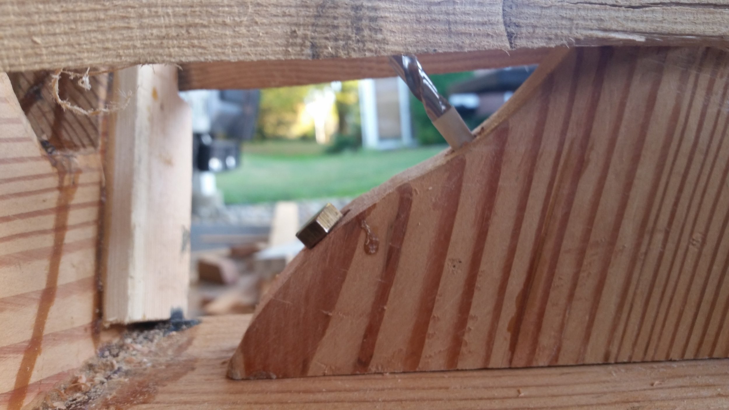
As you can see, the limiting factor to any bevel is the vertical components of this locker. They limit how much each support can be rotated in relation to the dimensions needed for the bilge pump.

To accommodate the bevel, the small brass screws were removed and re-drilled into the new position. The inboard support needed to be sawed a bit to allow the board to rotate in the box. The supports were rotated until they were set on an equal incline, allowing the bilge pump to sit flat on the boards with an inboard tilt. Since the pump is large, heavy, and bulky, I chose to use a small scrap of 2x4 that is much lighter and would allow me to evaluate the incline without much fuss. 

Once the boards were aligned with each other, pilot holes were made to mark the locations of the through bolts. With the pump removed, the holes were drilled out all the way to allow the insertion of 1/4" through bolts.

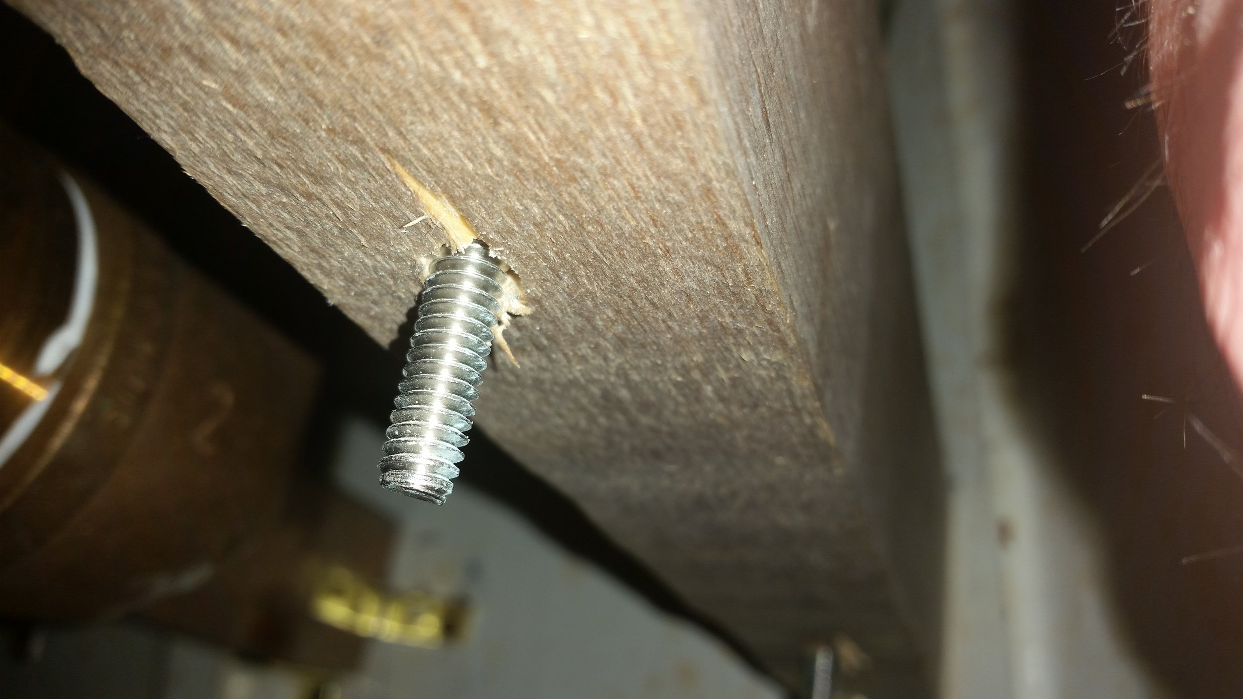
The reason the frames need to be beveled is because the bolts need as much material to grab onto. If I through bolted at an angle on vertical frames, the bolt would exit the side of the frame and be severely weakened. By rotating the frames, the through bolts exit the bottom squarely and securely. 

Above the frame, the head of the bolt is supported by a finish washers to be a bit more lenient with angulation of the bolt against the bronze flange of the pump body.

The tiny brass screws that are supporting the frames at the moment are by no means strong enough to support the forces that the bilge pump will exert on them while operating. These tiny screws are simply being used to help position the frames during the construction process.

Stem and Knee

With both rabbet lines cut into the stem and all the angles between it and the knee perfected, it was time to connect the components. The stem knee was positioned between the chine logs and dry fitted with the stem to identify its ideal location.

Pilot holes were then drilled through the stem and into the keel timber. The first pilot hole was drilled all the way through and into the keel, allowing me to place the bronze lag bolt that would hold the knee in place during the rest of the procedure. With the stem knee immobilized, I was able to safely drill the subsequent pilot holes. 

Drilling a pilot hole is a simple task, until you consider the length of wood you need to drill through. To allow the drill bit to reach the length at hand, I needed to use extra long drill bits. In my case, a 12 inch long drill bit did the task well. I placed tape on the drill bit to alert me that I have gone to the required depth. 

The procedure was repeated on the stem, allowing me to dry fit and verify everything before glue and time constraints were introduced. Once I was certain that everything lined up perfectly and squarely, I disassembled the entire unit and applied wood glue and bedding compound in their appropriate places. 

Wood glue was placed on surfaces that will not be exposed to the outside edge of the hull and bedding compound was placed where the edge would be exposed to the water. The stem received polysulfide bedding compound on its faying surface while the knee received wood glue on its faying surfaces. When the rabbet is cut into the keel the junction between the stem and keel will be exposed to the water outside of the hull, necessitating the need for polysulfide bedding compound here to prevent leaks in the future.

Circling Fish

Some days, the smaller things catch your eye when you are on the water. Walking down the pier towards the boat, Maddie noticed that the fish were swimming in a circle and forming a weak whirlpool.

Morty was mystified by the swirling school of fish right by the edge of the pier. We all watched as they swam around in circles, slowly moving the school further from the pier until they all dove deep under water and out of sight.

These are the smaller features of life aboard that would be missed by the average land lubber who is all caught up in their schedule and the hurry of daily life. Instead, we stood on the edge of the pier and watched the fish play out for a few moments before continuing our walk toward the boat. No rush and no worries, as all our worries were left on shore!

Electronic Space Heaters

Electric space heaters are great for instant localized heat. They can heat up a tiny cabin or a small part of a larger space in a few minutes. While they may seem like the perfect answer to your heating needs, they do have some downsides.

They are a huge fire hazard. They produce so much heat that they can not be aimed too closely towards flammable materials, such as drapes or wood structures. On a boat, this is pretty much the entire structure! 

They are also a tipping hazard, which then contributes to the fire hazard problem. If a storm kicks up waves or a wake rolls through, the top heavy heater could fall over and start a fire. Some heaters contain shut off switches if they sense that they have tipped over, which is a very important safety feature, but still no excuse for unsupervised use.

Because of these problems, you should never leave a space heater unattended. If a problem were to occur, you need to be there to rectify it immediately.

We keep two space heaters on board, one from Walmart (we went through three before we found one that worked very well, the others didn't hold up) and one from West Marine.

The West Marine heater works wonderfully! It's called the Cube and uses a ceramic core heater. Its tip sensor works reliably (I actually test them out). If you tip it over about 30 degrees, it will turn off. The Walmart one (Holmes) will keep running after it has fallen completely over.

The Walmart heater was a bit of random luck. I would buy a heater and find that it failed to deliver as promised, then I would buy another heater to come to the same conclusion. This was the fourth heater I bought, so I can't say that any heater will work as they all seem to be different. The Cube from West Marine does seem to be a reliable work horse. It was the first one I bought and it heats so wonderfully that I bought a second as a gift for my sister and that one also heated very well. 

If you are going to buy only one electric space heater, I recommend the Cube from West Marine. It is expensive compared to other units, but it is worth every penny when you feel warm and cozy on a cold day!

Electric space heaters are an excellent supplemental source of heat and are very useful to add heat to a localized area. When used in conjunction with the other heat sources aboard, it can create a very comfortable living environment while consuming minimal resources.

Smoothing the Transom

In the steps leading up to this point, there has been very little regard for keeping the planks fair to each other. They were jointed and surfaced with no regards for a plank thickness. When the dowel holes were drilled, they were positioned in the middle of the plank with no regards for uniform thickness or edge leveling.

The reason fairness was not a concern during the construction process is because the planks are way thicker than they need to be, so scrubbing off a bit of wood won't cause any detriment. Not being concerned about the fairness of the planks makes the construction process proceed very quickly and much more easily. If I had stressed about fairness in the planks, I would still have needed to do some final fairing in the end anyways. To make my life easier and the construction process speedier, I disregarded obsessive concern for fairness in the interim, while keeping everything more or less even as assembly progressed quickly.

The irregular plank thicknesses are grossly apparent between the planks and the assembled board is too large to fit through the bandsaw or the jointer, so I am left to fairing the surface smooth with hand tools.

A Stanley No. 4 Plane served to remove the gross amount of wood and bring the planks down to a close match. I then ran a jack plane diagonally across the board to fair everything up and make the entire assembly uniform. Setting the long jack plane on its side demonstrates any high spots that need extra attention. These areas could be reduced with the No. 4 plane and then faired in with the jack plane. Once everything was very smooth and level, I began sanding.

The board was sanded using a straight board wrapped in sand paper. The paper took down any last imperfection and blended the entire face together. The end result was a smooth and uniform surface on one side. 

After one side is smoothed to perfection, the board was flipped and the same procedure was carried out on the other side. This left us with a very smooth transom that is ready to be cut to its final shape and fitted to the stern.