

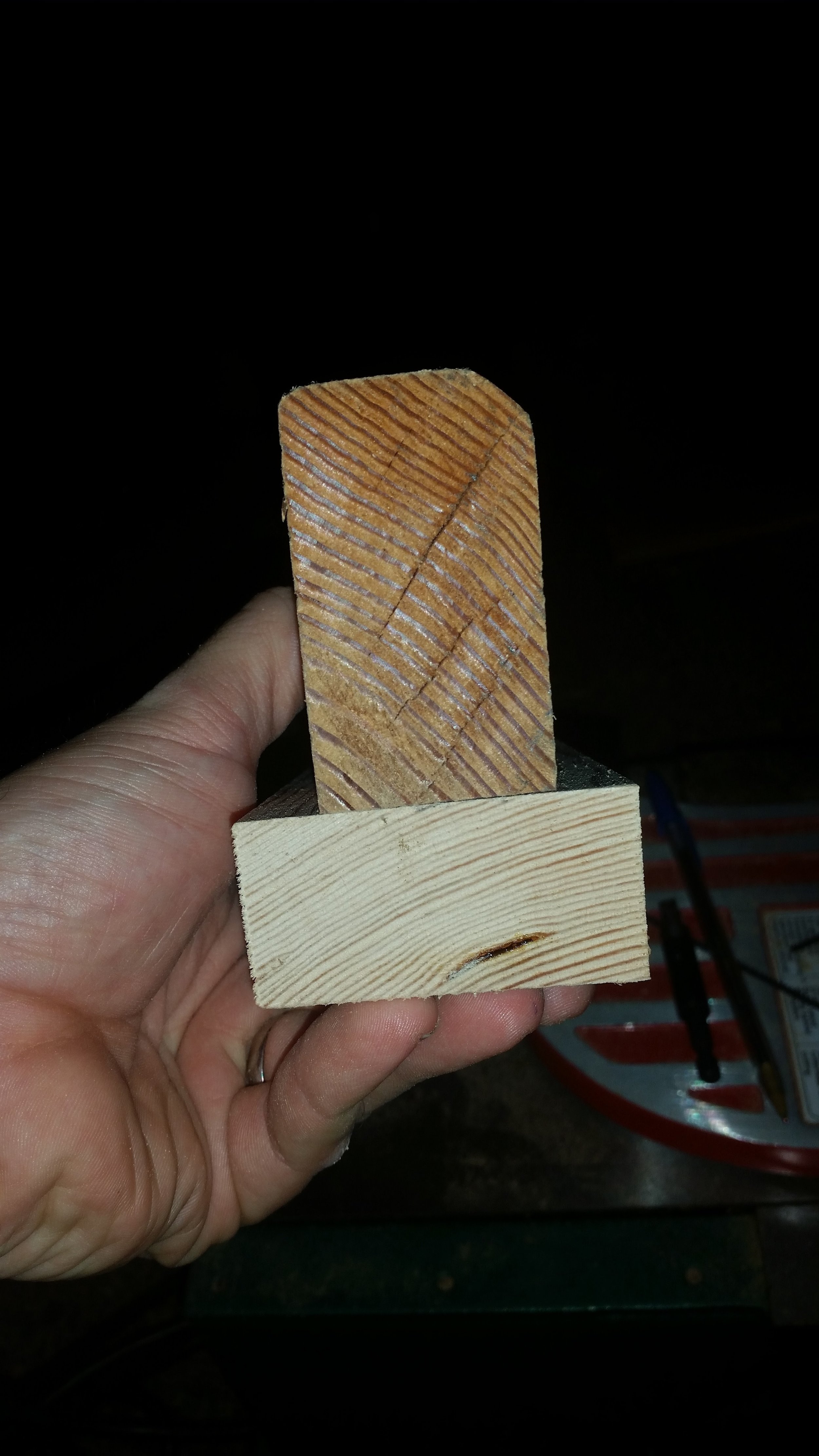
The stern knee is the structural support that helps transfer stress and loads from the stern post to the keel. It is made out of a single piece of wood that has vertical grain with a slight angle to it. The slight angle ensures that the medullary checking that will occur will form diagonally across the knee and not in the same direction as the fasteners.
The stern knee attaches to the end of the keel via a large and strong bronze lag bolt and to the stern post via four stout bronze screws. The transom planking will be attached to the stern post, transmitting it's loads to the keel via the stern knee. As you can see, this is a rather important structural member in the dinghy.
To add complexity to the fabrication process, the transom is going to be raked aft with a slop of five inches every twenty four inches. This angle will produce a gentle and pleasing to look to the slope of the transom. This angle is also ideal for. The mounting of an outboard motor, which we will do in emergency situations.
The stern knee and stern post need to mate perfectly flush with the flat keel. To get the angle of the sloping transom to mate perfectly with the flat keel, I used a variety of squares and calculations. I know that the freeboard is going to be eighteen inches high, so the sternpost was set in a square where the top of it passes over the eighteen inch mark. The bottom of the sternpost was scooted over to the three and three quarters mark, as this distance follows the same slope of five in twenty four. I pinched the stern post to the square and raised it off the surface just a bit so I could mark it from the underside with a pencil.
The line drawn on the side of the stern post now represents the correct angular orientation for the bottom of the sternpost to mate perfectly flat with the keel.
This line was cut on the bandsaw and then test fit to the keel. The top of the stern post was left much longer than needed as it is always easier to shorten a board than it is to make it longer. With the angled cut verified, I know that the stern post is long enough and angled properly.
The knee was cut out following the same slope line. The knee is six inches tall, so a slope of five in twenty four would mean that our six inch knee needs to slope over one and one quarter inch.
The block of wood was marked at the top at the six inch point and on the bottom at the on and one quarter inch mark. A straight edge connected the marks giving me the line to cut along to match the stern post's aft rake to the stern knee.
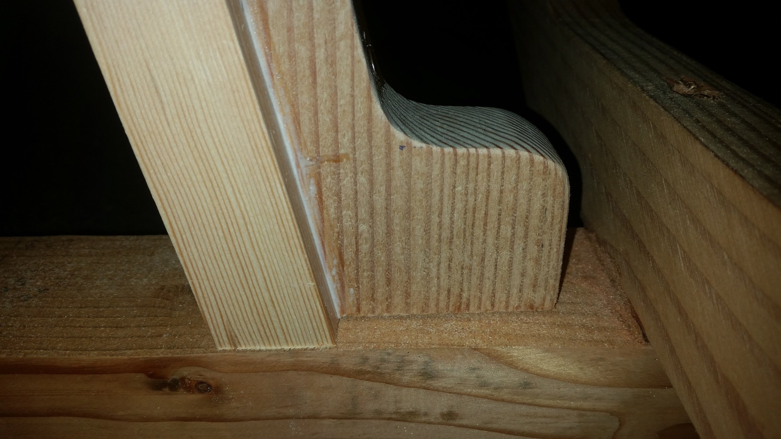
After cutting the knee along the line with the bandsaw, we the two pieces were test fitted. To properly test fit the stern post and stern knee, a square was used, as the top of the stern post should intersect the 18 inch mark and the bottom of the stern post lay flat on the bottom of the square. During the test, the stern post met the mark and the faying surface to the keel laid flat!
The two pieces were test fitted on the keel to verify that they are true and mate up to the faying surface of the keel properly.
Since they mated well, it was time to connect the stern knee to the stern post. I drilled pilot holes through the knee which will accept the bronze fasteners. The holes are set staggered to avoid causing a crack in the knee. If you set all four screws in a vertical line, the knee can split along the grain and fail its purpose. By staggering the screws placement, the rest of splitting the knee is greatly reduced.

With the holes drilled and any splinters sanded off, it is time to drill the pilot holes in the stern post. The top pilot hole was drilled by first marking the sternpost with the drill running in reverse. Running the drill in reverse minimizes the risk of the drill bit walking aroud, ruining your alignment. Running the drill in reverse will produce a very notable mare on the stern post. Once the stern knee is removed, you can mark your pilot hole without any risk of misalignment.
With the first hole ready, the stern knee was set back onto the post and the bronze screw was inserted most of the way. This will keep the entire unit aligned and in place while the other three holes are made.
With the top of the knee supported by the screw and the bottom of the knee supported by a clamp, the second pilot hole could be created in the lowest screw hole and its screw inserted. Now the knee is securely held in place and the last two pilot holes can be drilled at the same time to speed up fabrication time.
Now that the four holes have been drilled with accuracy, it is time to join the two pieces of wood.. The faying surfaces were coated with a liberal amount of Titebond III waterproof wood glue and some extra wood glue was set into the screw holes. The glue in the screw holes will coat the bronze fasteners as they are driven in and lock them into place as they coat the threads.

With all the surfaces ready for mating, the knee was aligned to the stern post and the four screws were driven home. The four screws will provide enough clamping force, negating the need to use external C-clamps. The excess wood glue squeezed out, ensuring that all the surfaces were sufficiently covered with glue and the excess was wiped off with a dry towel. The glue was then allowed to cure for the next two days without being disturbed.
